the12volt.com spacer
icon

Wiring Explanation, Compustar 4900S CM-900, 1997 Toyota 4Runner


Post ReplyPost New Topic
< Prev Topic Next Topic >
oakbehringer 
Member - Posts: 4
Member spacespace
Joined: October 07, 2019
Location: Illinois, United States
Posted: January 14, 2020 at 10:01 AM / IP Logged Link to Post Post Reply Quote oakbehringer
Hey people, I have a few basic questions for the Compustar 4900S (CM-900 brain) that I'm about to install on my 1997 4runner. It's a very basic vehicle with no existing alarm system or keyless entry, and no fob in the key..
This is my first RS or Alarm install, so please bear with me as I ask dumb questions regarding the wiring as explained in the manual.
Pin 2 Green/White – This is the positive (+) parking light wire that triggers when you lock and unlock the doors and remote start the vehicle.
This is stating that the CM-900 will output 12v + through this wire when you press the unlock or start buttons, right? So I should run this to the + brake light wire for my vehicle, right?
Pin 1 Red - Constant 12V positive (+) power input. This wire must be connected. The proper vehicle wire will test (+) 12V at all times - while the key is in the off position, the on position and during
crank.
Pin 3 Red/White - Constant 12V positive (+) power input. This wire must be connected. The proper vehicle wire will test (+) 12V at all times - while the key is in the off position, the on position and
during crank.
Two wires with the same description, both with a 30A inline fuse. Is it recommended that I simply run a wire through the firewall capable of handling 60A that these both can splice into? Or would that do I connect to the main wire going to the fuse panel?
Blue - Positive 12V (+) output that powers up during remote start. The behavior of this wire is selectable by a jumper inside the control module. By default this wire powers up as a 2nd Ignition trigger. It is changeable to a 2nd Starter or 2nd Accessory.
If I'm reading this correctly, I can disregard this wire.
Yellow - Starter 12V positive (+) output. This wire must be connected for remote start. The proper wire will test 0V with the key in the off position, 0V while the key is in the on position and (+) 12V during crank.
I need to run this wire to the wire that triggers the starter; this is the same wire that is connected when I turn the key to "start." Correct?
Last question, is there anyway of knowing if tachless sensing will work with my vehicle? Or do I simply have to try it out?
Thanks you! I really appreciate the guidance.
kreg357 
Platinum - Posts: 7,787
Platinum spaceThis member has made a donation to the12volt.com. Click here for more info.spaceThis member has been recognized as an authority in Electrical Theory. Click here for more info.spaceThis member has been recognized as an authority in Mobile Security and Convenience. Click here for more info.spacespace
Joined: January 30, 2009
Location: Pennsylvania, United States
Posted: January 14, 2020 at 3:27 PM / IP Logged Link to Post Post Reply Quote kreg357
If you have never done a Remote Start install, you are in for some fun.Luckily, as you mentioned, your vehicle is very basic. You are beginningproperly by spending a good bit of time planning the process and learningabout the R/S system and your vehicle. First you want to find all the wiring info other people and companies haveposted about your vehicle. Being as it is older and very basic there should>be plenty of info to assist you. Here is a link to a decent source of info : http://diagrams.marktoonen.nl/printlist.aspx?MakeID=2&ModelID=12524 Bulldog Security indicates that your vehicle does not have an ignitionimmobilizer system like most newer vehicles. This will save you some time>and money as you won't need a bypass module. You mentioned that the 4Runners does not have RKE but does it havepower locks? The R/S system you have can support RKE on the aftermarket 4 button FOBs if you have power locks. It's just two extra>connections to get that feature and a nice upgrade. To answer some of your questions... The Parking Light output is used to flash the parking lights in responseto your remotes commands. This wire needs to be connected to the vehiclesparking light wire, not the Brake wire. You can use either the (+) or the>(-) Parking Light output but not both. I would go with the (-) output tothe Red/White wire at the Headlight plug in the steering column. As for the two Red fused power input wire, those would go to the vehiclesWhite and White/Red wires at the main ignition switch connector as indicatedin the wire chart. Being as your vehicle has 2 Ignition wire, Black/Yellow and Black/Yellow orBlack/Red at the main ignition switch connector, you will use the R/S's BlueIGN2 programmable wire for the IGN2 wire. No programming or strapping>changes needed. Yes, the Yellow Starter wire goes the Black Starter wire at the main ignitionconnector. While you might have good results with running in Tachless Mode, I would>run the R/S's Tach wire to engine diagnostic plug as shown in the BulldogSecurity info. My suggestion would be to make up a wire connection chart with yourproposed wiring and post it here for Forum Member review. This willprevent any problems and or damage to vehicle and R/S when you doperform the actual install.
Soldering is fun!
oakbehringer 
Member - Posts: 4
Member spacespace
Joined: October 07, 2019
Location: Illinois, United States
Posted: January 15, 2020 at 2:44 PM / IP Logged Link to Post Post Reply Quote oakbehringer
Incredible, thank you Kreg. I had actually worked most of this out on my own since my OP, but had disregarded the blue wire, and had the blower wire wrong. Thank you for the link - that's a HUGE help!
I plan on making the power locks work, no problemo.
One question on these diagrams/charts, just for my sanity/clarity: When I see something like this on the vehicle's chart:
Power Unlock: Red/Yellow (-)
Does that mean that the wire is running to the ground/negative battery terminal? Or does it mean that connecting it to ground will trigger the locks?
Thanks!
Adam
kreg357 
Platinum - Posts: 7,787
Platinum spaceThis member has made a donation to the12volt.com. Click here for more info.spaceThis member has been recognized as an authority in Electrical Theory. Click here for more info.spaceThis member has been recognized as an authority in Mobile Security and Convenience. Click here for more info.spacespace
Joined: January 30, 2009
Location: Pennsylvania, United States
Posted: January 15, 2020 at 5:47 PM / IP Logged Link to Post Post Reply Quote kreg357
The polarity marked by the wire in the Bulldog info denotes the signal polarity seen when the vehicle uses that wire. In the case of the Power Unlock wire, you would see a (-) signal on the wire when you press the door unlock button. For the R/S to use that control wire, the R/S would have to output a (-) signal on it's Unlock wire ( which is always marked on the R/S Install guide / diagram ). All that would be required for the R/S system to perform RKE functions is a direct connection between the R/S lock wires to the correct vehicle wires shown in the Bulldog info.
You will need a Digital Multi Meter to locate and test these (-) wires. DMM setup, 20 Volts DC, Red test lead to +12V constant and Black test lead to the suspect wire. Press the corresponding lock or unlock door button and the DMM goes to 12 volts.
Soldering is fun!
oakbehringer 
Member - Posts: 4
Member spacespace
Joined: October 07, 2019
Location: Illinois, United States
Posted: January 16, 2020 at 11:41 AM / IP Logged Link to Post Post Reply Quote oakbehringer
Thanks Kreg, you're a huge help.
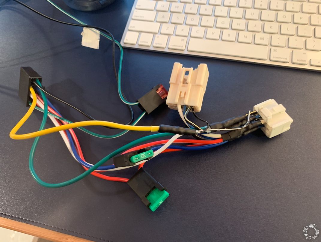
I lucked out and found this jumper in my "random parts pile," from the long-removed factory alarm, that goes between the ignition switch and factory harness. As a result, I was able to do most of of the soldering in the comfort of my home (it's 15 degrees outside), and without touching the harness that's in my truck.
Just have to get out there and do the locks, tach sensor, parking lights, and ground. I'll let you know how it turns out!
Wiring Explanation, Compustar 4900S CM-900, 1997 Toyota 4Runner -- posted image.
oakbehringer 
Member - Posts: 4
Member spacespace
Joined: October 07, 2019
Location: Illinois, United States
Posted: January 27, 2020 at 10:55 AM / IP Logged Link to Post Post Reply Quote oakbehringer
Got everything working, thanks again for the tips.

If you wish to post a reply to this topic, you must first login.
If you are not already registered, you must first register.

  Printable version Printable version Post ReplyPost New Topic
You cannot post new topics in this forum
You cannot reply to topics in this forum
You cannot delete your posts in this forum
You cannot edit your posts in this forum
You cannot create polls in this forum
You cannot vote in polls in this forum

  •  
Search the12volt.com
Follow the12volt.com Follow the12volt.com on Facebook
Thursday, May 16, 2024 • Copyright © 1999-2024 the12volt.com, All Rights Reserved Privacy Policy & Use of Cookies
Disclaimer: *All information on this site ( the12volt.com ) is provided "as is" without any warranty of any kind, either expressed or implied, including but not limited to fitness for a particular use. Any user assumes the entire risk as to the accuracy and use of this information. Please verify all wire colors and diagrams before applying any information.

Secured by Sectigo
the12volt.com spacer
Support the12volt.com
Top
the12volt.com spacer