the12volt.com spacer
icon

passlock 1


Post ReplyPost New Topic
< Prev Topic Next Topic >
muaiad97 
Copper - Posts: 207
Copper spacespace
Joined: April 08, 2003
Location: Canada
Posted: December 20, 2003 at 3:36 PM / IP Logged  

Hi  all

pleas anyone can tell me how much the resistor in this passlock 1.

or i have to mesure it .the car its sunfire 98.

passlock 1 -- posted image. 

JeremyB 
Member - Posts: 18
Member spacespace
Joined: December 15, 2002
Location: United States
Posted: December 20, 2003 at 4:01 PM / IP Logged  
You have to measure. There are bypass modules around that you just wire them up and after you start the vehicle a few times with the key will learn the resistance needed
jrilla 
Gold - Posts: 1,498
Gold spaceThis member has made a donation to the12volt.com. Click here for more info.spacespace
Joined: November 19, 2002
Location: North Dakota, United States
Posted: December 20, 2003 at 7:34 PM / IP Logged  
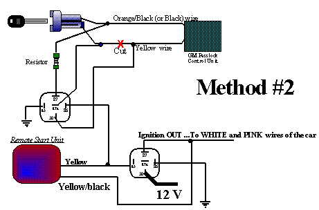
Take a look at the upper right diagram on this link (Diagram #3):
Passlock I temporary bypass (diagram #3)
To get the resistence value: Strip back the Black wire (ORANGE / Black on Trucks). Start the car with the key, then cut the yellow passlock wire. strip back the key side of the yellow wire and take a DMM and put one lead on the key side of the yellow wire and the other on the ORANGE / Black wire. Record the resistence, then reverse the two leads and record the resistence. Dial in the higher of the two resistences recorded into a trimpot (or buy a resistor within 5% of the measured value) and set it up using two standard 30 amp automotive relays according to the diagram
J Rilla
Owner/Installer
muaiad97 
Copper - Posts: 207
Copper spacespace
Joined: April 08, 2003
Location: Canada
Posted: December 23, 2003 at 9:34 PM / IP Logged  

thank u

#87 is it  ground  in that diagram .

jrilla 
Gold - Posts: 1,498
Gold spaceThis member has made a donation to the12volt.com. Click here for more info.spacespace
Joined: November 19, 2002
Location: North Dakota, United States
Posted: December 24, 2003 at 12:17 AM / IP Logged  
Umm, 87 on the left relay goes to the bulb test wire which is located in the same connector as the Red 12v+ constant wires at the key cylinder.
J Rilla
Owner/Installer

Sorry, you can NOT post a reply.
This topic is closed.

  Printable version Printable version Post ReplyPost New Topic
You cannot post new topics in this forum
You cannot reply to topics in this forum
You cannot delete your posts in this forum
You cannot edit your posts in this forum
You cannot create polls in this forum
You cannot vote in polls in this forum

  •  
Search the12volt.com
Follow the12volt.com Follow the12volt.com on Facebook
Friday, May 10, 2024 • Copyright © 1999-2024 the12volt.com, All Rights Reserved Privacy Policy & Use of Cookies
Disclaimer: *All information on this site ( the12volt.com ) is provided "as is" without any warranty of any kind, either expressed or implied, including but not limited to fitness for a particular use. Any user assumes the entire risk as to the accuracy and use of this information. Please verify all wire colors and diagrams before applying any information.

Secured by Sectigo
the12volt.com spacer
Support the12volt.com
Top
the12volt.com spacer