the12volt.com spacer
icon

Door Triggers - 1991 Mercedes


Post ReplyPost New Topic
< Prev Topic Next Topic >
eiknujrac 
Member - Posts: 49
Member spacespace
Joined: October 30, 2004
Posted: November 07, 2004 at 12:38 AM / IP Logged  
On my car, a 1991 Benz 300E, I have two different connections for door triggers at the alarm. One is for the rear, and the other is for the front. They Both show (+) when closed, and (-) when open. To connect both these wires to the single input on the alarm, would I use a pair of diodes? If so, how many amps (I have a pair of 6 amps left over from parking lights)? And last question, would the stripe be pointed at the alarm or at the triggers?
Ben.c 
Member - Posts: 29
Member spacespace
Joined: October 30, 2004
Location: Australia
Posted: November 07, 2004 at 4:23 AM / IP Logged  

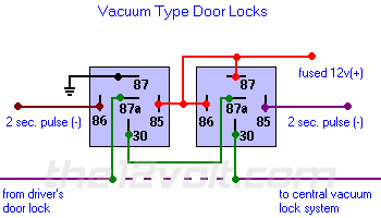
Door Triggers - 1991 Mercedes -- posted image.

 The vehicle should have vacuum locking and you will need to follow the above diagram to hook up locking ther should be a blue or green wire going to the vacuum pump witch is located under the rear seat you will have to cut this wire and place it in the circuit as illustrated. ( this wire will show a 12 + on lock or unlock but will show a 12v - in the opposite state. The alrm or keyless entry system you are fitting must have a selection to have a neg pulse of at least 2 seconds , if it doesn't you will have to place some kind of timer into the circuit.

ozy installer
eiknujrac 
Member - Posts: 49
Member spacespace
Joined: October 30, 2004
Posted: November 07, 2004 at 10:56 AM / IP Logged  
I'm sorry if I confused anyone, I meant the Door Pins, that show a (-) When the door is open and a (+) when they are closed. I have 2 different wires, one for both rear doors, and one for both front doors. I was wondering how to connect them to the single input on my alarm module.
mo12v 
Platinum - Nominee - Posts: 2,748
Platinum - Nominee spaceThis member consistently provides reliable informationspace
Joined: September 30, 2003
Location: Afghanistan
Posted: November 07, 2004 at 11:19 AM / IP Logged  
They are (-) negative trigger........The reason it shows + when you close the door is because it is feeding off the other half of dome light which is the + feed
Hook your Door Pin wire from Alarm that is Negative trigger
MO
Don't Learn from Others Mistakes
You Might Be the One That Knows.
eiknujrac 
Member - Posts: 49
Member spacespace
Joined: October 30, 2004
Posted: November 07, 2004 at 12:07 PM / IP Logged  

I know, but I have two separate wires, not a common wire for the door pins. One wire for both rear doors, and one for both front doors. I only have 1 input on the alarm, but two outputs from the door pins. I know if i just twist these together and connect them weird things could happen, so do I need to use a pair of diodes? If So, what amperage ( I have two 6 amps left over from parking lights).

THANKS!

eiknujrac 
Member - Posts: 49
Member spacespace
Joined: October 30, 2004
Posted: November 07, 2004 at 1:40 PM / IP Logged  

Anyone? My install is on hold till i figure this out.

hagmanti 
Silver - Posts: 304
Silver spacespace
Joined: September 14, 2004
Location: United States
Posted: November 07, 2004 at 2:01 PM / IP Logged  
Put the stripe facing the door trigger wire. The side that is striped should be closest to negative triggers.
Me
eiknujrac 
Member - Posts: 49
Member spacespace
Joined: October 30, 2004
Posted: November 07, 2004 at 2:16 PM / IP Logged  
Thanks!

Sorry, you can NOT post a reply.
This topic is closed.

  Printable version Printable version Post ReplyPost New Topic
You cannot post new topics in this forum
You cannot reply to topics in this forum
You cannot delete your posts in this forum
You cannot edit your posts in this forum
You cannot create polls in this forum
You cannot vote in polls in this forum

  •  
Search the12volt.com
Follow the12volt.com Follow the12volt.com on Facebook
Friday, May 3, 2024 • Copyright © 1999-2024 the12volt.com, All Rights Reserved Privacy Policy & Use of Cookies
Disclaimer: *All information on this site ( the12volt.com ) is provided "as is" without any warranty of any kind, either expressed or implied, including but not limited to fitness for a particular use. Any user assumes the entire risk as to the accuracy and use of this information. Please verify all wire colors and diagrams before applying any information.

Secured by Sectigo
the12volt.com spacer
Support the12volt.com
Top
the12volt.com spacer