the12volt.com spacer
icon

72 Monte Carlo door lock problem


Post ReplyPost New Topic
< Prev Topic Next Topic >
turbonaolds 
Member - Posts: 4
Member spacespace
Joined: February 01, 2005
Location: United States
Posted: February 01, 2005 at 10:12 PM / IP Logged  

I am trying to replace an old alram with a slightly newer one in my 72 Monte Carlo.

The car originally came with power locks. The old alarm was wired to some relays (Bosch 20/30) behind the door. The door locks functioned fine with it. I hooked up a Viper C60 today and the doors won't lock or unlock nor will the alarm set when the doors are shut. Everything works fine if the door is open.  I did connect the wiring  the same as the old alarm (bith had the connections marked the same.

I have been messing with this most of the day and tried different thing but same result or nothing.

I will go out and try to get more info now as far as how it was connected and add but if anyone has any ideas let me know.

Thanks,

         Jason

turbonaolds 
Member - Posts: 4
Member spacespace
Joined: February 01, 2005
Location: United States
Posted: February 01, 2005 at 10:42 PM / IP Logged  

here is the schematic on the bottom of the brain;

Harness 1

orange: (-)ground when armed

white (+) light flash output

Blue/white: (-)low voltage output

gray: (-) valet switch

Green: (-) door switch input ------ NOT CONNECTED! Tried to connect to relay or in place of other wires but nothing works

Blue: (-) sensor switch input zone 3

violet:  (+) Door switch input (zone 3)

Black: chassis grnd

Yellow: (+) switched 12 volt

Brown: (+) siren output

Red: (+) 12 v

RED / White: (-) channel 2 output -------NOT CONNECTED

    Harness 2 Bottom Row;

(A) Brown; unlock #87A, normally closed

(B) Violet; unlock #87 norm open input ---------Used (also connected to (E) - connected to door pin switch

(C) Blue; unlock #30, common, output    ---------USED - Connected to Relay

(D) White: lock, #87A, normally closed

(E)Violet; lock #87, normally open input

(F) Green; lock #30, common output------------Used- connected to Relay

                         TOP ROW;

G/H; green, starter kill #1

J/K; green, starter kill #2

L; White (-) Courtesy output (30 sec)

M; WHITE/ Blue; Channel 3 output

Relays are Bosch part # 0 332 204 150

Locks work fine by door switch.

I know I am missing somehing simple please don't be afraid to point it out guys.

turbonaolds 
Member - Posts: 4
Member spacespace
Joined: February 01, 2005
Location: United States
Posted: February 02, 2005 at 12:43 AM / IP Logged  

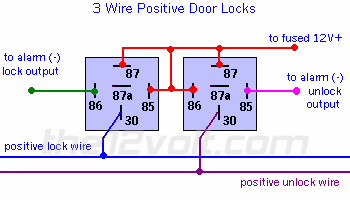
72 Monte Carlo door lock problem -- posted image.

I was looking at this and these appear to be the relays I have. On my relays they were already wired as both #86 going to the alarm output wires could this be the problem?

KarTuneMan 
Platinum - Posts: 7,056
Platinum spaceThis member has made a donation to the12volt.com. Click here for more info.spaceThis member consistently provides reliable informationspace
Joined: December 14, 2004
Location: Isle Of Man
Posted: February 02, 2005 at 10:39 AM / IP Logged  

85 and 86 can be flip flopped. Its done like that in the picture to make it easier to hook wires too.....Imagin what a mess it would look like if on both relays as they sit here, you tried to sneak 12 volts to 87 and 85 on both, also the trigger wir being on both 86...it would be a mess  

85  and 86 control the power coil inside the relay,and poarity is NOT an issue. See the can be flip flopped

turbonaolds 
Member - Posts: 4
Member spacespace
Joined: February 01, 2005
Location: United States
Posted: February 03, 2005 at 1:47 AM / IP Logged  

I found it! I switched the wires to resemble the diagram and then found I had the violet wire connected to the pin lock instead of the green (-) trigger lead. Connected violet to ground and all works fine. This was my first alarm install ever.

Thanks for the help. Nice site you have here I learned alot last night searching for my problem.


Sorry, you can NOT post a reply.
This topic is closed.

  Printable version Printable version Post ReplyPost New Topic
You cannot post new topics in this forum
You cannot reply to topics in this forum
You cannot delete your posts in this forum
You cannot edit your posts in this forum
You cannot create polls in this forum
You cannot vote in polls in this forum

  •  
Search the12volt.com
Follow the12volt.com Follow the12volt.com on Facebook
Monday, May 27, 2024 • Copyright © 1999-2024 the12volt.com, All Rights Reserved Privacy Policy & Use of Cookies
Disclaimer: *All information on this site ( the12volt.com ) is provided "as is" without any warranty of any kind, either expressed or implied, including but not limited to fitness for a particular use. Any user assumes the entire risk as to the accuracy and use of this information. Please verify all wire colors and diagrams before applying any information.

Secured by Sectigo
the12volt.com spacer
Support the12volt.com
Top
the12volt.com spacer