the12volt.com spacer
icon

central locks


Post ReplyPost New Topic
< Prev Topic Next Topic >
paultheboy 
Member - Posts: 3
Member spacespace
Joined: November 29, 2002
Location: United Kingdom
Posted: December 08, 2002 at 5:48 AM / IP Logged  
hello mate me again i have another one for you, on my alarm i have 1 grounded when armed wire (orange) but on my locks i have 2; white (lock) brown (unlock) for a remote control system could you please tell me what diagram i would need to use  P.S. there are 5 wires going to each side on the front locks and 2 on each going to the rear  so a total of 9 wires exiting the actuator control modual. P.P.S.this is not a duplicate thanks > paul
10nesne1 
Silver - Posts: 284
Silver spacespace
Joined: June 19, 2002
Location: British Columbia, Canada
Posted: December 08, 2002 at 10:05 AM / IP Logged  

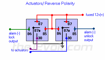
Well, if you are installing a central locks on your vehicle.  The Front Door Actuators will have 5 wires because inside the Front Door Actuators has two micro switches for lock and unlock like the power door lock switch on the driver and passenger doors.  When you buy a central door lock kits for two or four doors, it comes with a relay module.  This you will have to follow the diagram and connect all the wires to the relay module.  The rear door lock actuator only has two wires because those are the normal actuators.  If you don't have the central door lock relay module then you don't have to hook up the Orange, White, and Brown wires.  You can hook up all four doors to an alarm or keyless entry system.   Here is a diagram allow you to connect to an alarm or keyless entry system.   Just ignore the three other wires.

central locks -- posted image.Actuators / Reverse Polarity
This is practically identical to the 5 wire alternating 12V(+) system above. The only difference is there's no switch! Both motor legs rest at ground at the relays. To lock or unlock the vehicle, polarity is changed on one motor leg.

central locks -- posted image.

Sorry, you can NOT post a reply.
This topic is closed.

  Printable version Printable version Post ReplyPost New Topic
You cannot post new topics in this forum
You cannot reply to topics in this forum
You cannot delete your posts in this forum
You cannot edit your posts in this forum
You cannot create polls in this forum
You cannot vote in polls in this forum

  •  
Search the12volt.com
Follow the12volt.com Follow the12volt.com on Facebook
Sunday, May 19, 2024 • Copyright © 1999-2024 the12volt.com, All Rights Reserved Privacy Policy & Use of Cookies
Disclaimer: *All information on this site ( the12volt.com ) is provided "as is" without any warranty of any kind, either expressed or implied, including but not limited to fitness for a particular use. Any user assumes the entire risk as to the accuracy and use of this information. Please verify all wire colors and diagrams before applying any information.

Secured by Sectigo
the12volt.com spacer
Support the12volt.com
Top
the12volt.com spacer