the12volt.com spacer
icon

Car alarm model hs-100


Post ReplyPost New Topic
< Prev Topic Next Topic >
rollasport 
Member - Posts: 1
Member spacespace
Joined: July 18, 2006
Location: United States
Posted: July 18, 2006 at 9:44 PM / IP Logged  

I have purchased this car alarm and i'm connecting it to my2000 chevy astro van. I am having a hard time with the relay and the the connection to the door lock system. The onlt thing the paperwork states is to check the polarities. What is a polarity? I have a voltometer but everything is reading the same. The door lock wiring consists of  6 wires. white, yellow orange and three others same as before but with the black stripe. OK I know there are ground and + wires. Does anyone have the exact wiring way for a 2000 conversion Astro van that did not bring the remote lock and unlock from the factory. Also the relay has four wires (yellow, white and 2 green). The diagram shows the yellow goes to the main alarm box, and one of the green goes to the IGN.CYT.CJT high coil ( what is this?). and no other photo for the other green or white wire. I have only done other vehicles with more simpler alarms. Most have been toyotas. This is the first GM vehicle.

Is there any diagrams that I may follow? That are more legible.

Please help. Very confused

KarTuneMan 
Platinum - Posts: 7,056
Platinum spaceThis member has made a donation to the12volt.com. Click here for more info.spaceThis member consistently provides reliable informationspace
Joined: December 14, 2004
Location: Isle Of Man
Posted: July 18, 2006 at 10:52 PM / IP Logged  

The door lock wires from the alarm will be listed as N.O., N.C., and common. These represtent the pins on a standard relay. Your unit has built in relays.

N.O. is pin 87, N.C. is pin 87a, and common is pin 30. The lock wires on the van are POS(+) take the N.O. (pin 87) to 12volts constant. You will not use the N.C. (pin87a) take common to the wires in the van. Lock is blue, unlock is white, found in the drivers kick.

boki 
Member - Posts: 3
Member spacespace
Joined: January 02, 2006
Location: Bosnia Hercegovina
Posted: August 02, 2006 at 4:59 PM / IP Logged  
Please,I need Installation instruction for this alarm (CAR ALARM HS-100)
KarTuneMan 
Platinum - Posts: 7,056
Platinum spaceThis member has made a donation to the12volt.com. Click here for more info.spaceThis member consistently provides reliable informationspace
Joined: December 14, 2004
Location: Isle Of Man
Posted: August 03, 2006 at 1:00 AM / IP Logged  

What is a polarity?

I would suggest getting some assistance on this installation. This is a basic term...if you are unaware of it's meaning...I believe you need some help. Just to be sure there are no problems that could cause some REAL damage....

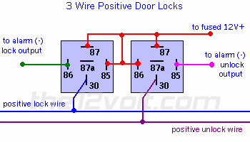
If you need to do it your self, heres a diagram for the relays to do your locks...just re-read my post on the lock wires from your alarm.

Car alarm model hs-100 -- posted image.

Take the wires labeled NO (pin 87)for BOTH and wire them to 12v fused. then take the common and go to the lock wires. one to lock (the lock wire from the alarm) and one to unlock (the other wire from the alarm) This is positive trigger locks with an alarm with built in relays. REMEMBER, your alarm controls 85, and 86....so ther is NO connection.

I hope this helps

matchnbpm 
Member - Posts: 3
Member spacespace
Joined: September 28, 2005
Location: United States
Posted: August 07, 2006 at 1:33 PM / IP Logged  

The instructions for the HS-100 is one of the worse translations from chinese to english I have ever seen.

From looking at the instructions, looks like the color codes go like this:

From alarm:

12volt - Red

Ign - White

Armed Output - Yellow

Door Trigger (-) - Blue

Door Trigger(+) - Orange

Trunk Trigger - None

Trunk Relase(+) - Green

Brown(there are 2, both are same) - Parking lights

Siren(+) - Pink

Ground - Black

Door locks:

Negative - dont use orange and ORANGE / black, tie yellow and yellow/black to ground, white is lock and WHITE/ black is unlock

Positive - dont use orange and ORANGE / black, tie yellow and yellow/black to 12v, white is lock and WHITE/ black is unlock

Havent installed this one yet, so take this info as is. Just translating from the manual


Sorry, you can NOT post a reply.
This topic is closed.

  Printable version Printable version Post ReplyPost New Topic
You cannot post new topics in this forum
You cannot reply to topics in this forum
You cannot delete your posts in this forum
You cannot edit your posts in this forum
You cannot create polls in this forum
You cannot vote in polls in this forum

  •  
Search the12volt.com
Follow the12volt.com Follow the12volt.com on Facebook
Sunday, May 5, 2024 • Copyright © 1999-2024 the12volt.com, All Rights Reserved Privacy Policy & Use of Cookies
Disclaimer: *All information on this site ( the12volt.com ) is provided "as is" without any warranty of any kind, either expressed or implied, including but not limited to fitness for a particular use. Any user assumes the entire risk as to the accuracy and use of this information. Please verify all wire colors and diagrams before applying any information.

Secured by Sectigo
the12volt.com spacer
Support the12volt.com
Top
the12volt.com spacer