the12volt.com spacer
icon

2000 honda civic, autopage 860


Post ReplyPost New Topic
< Prev Topic Next Topic >
pcmofo 
Member - Posts: 9
Member spacespace
Joined: October 29, 2006
Location: United States
Posted: November 03, 2006 at 1:37 AM / IP Logged  
So I have an Autopage 860 on its way to me shortly and I am debating if I should install it my self or not. Check out my Web Site for more info about my car and experience with electronics. I just installed a remote starter/keyless entry in my parents toyota van last weekend and it wasnt too bad. (besides the trip to the hospital to glue my finger back together, but thats another story) I have no problem with the wireing aspect. And doing my parents van gave me a good idea of what is in store in installing a system. Theirs was a cheap 50$ system and no alarm. I have all the spec sheets for my car and the system (from this site) and grasp the concept of what I am doing but since I have never done something like this is it a good idea?
I called around and $160 is the lowest I can get someone to install this system for me. Assuming I choose to install the system my self what are some important things I will need to know besides the obvious connect this wire to that wire... here are some questions I have
How do you splice into and secure the wires? I have been razor cutting or using a wirestripper then just wrapping the wires together then electrical tape and zip tie. Is there a better way to cut away the shielding? Should I solder or just twist wires together?
Does anything need to be mounted in a certian fashion? the knock window sensor, antenna placement, hood pin etc
Does autopage provide any kind of warrentee against the system failing to protect my car? if so does that only mean when it is installed by a pro? What about for insurance discount (passave arming discount)
Where do I mount the shock sensor, temp sensor, and valet button?
These are about all the questions I can think of at the moment. Check out my web site for lots more pics of my car so you can see what I am dealing with here. i can also post any pics of parts of the car you may need to see.
Thanks for your input :-)
KarTuneMan 
Platinum - Posts: 7,056
Platinum spaceThis member has made a donation to the12volt.com. Click here for more info.spaceThis member consistently provides reliable informationspace
Joined: December 14, 2004
Location: Isle Of Man
Posted: November 03, 2006 at 8:34 AM / IP Logged  

solder all your connections.

the knock sensor, put it on the windscreen, down by the dash. the antenna, up high centered on the glass hood pin, where you can.

you'll need to contact autopage, AND your insurance company.

The shock sensor...when you drop the dash appart, you'll see several places for poss. location (lots of harnesses, and flat spots)

valet, out of site.

pcmofo 
Member - Posts: 9
Member spacespace
Joined: October 29, 2006
Location: United States
Posted: November 04, 2006 at 11:00 AM / IP Logged  
The instructions say to mount the antenna pointing up and on the left side of the whinshield. it seems more practical to mount it behind the rearview mirror in the center of the window with the antenna point down... thoughts?
What connections can I leave out? I know I dont need a security bypass module etc. do I need to connect the tach? is the antenna going to cause interferiance with my GPS antenna or radar detector etc. the gps is in the center where dash meets the window and radar dector will be up by rearview mirror. Will running a power wire for the radar dector from the dash up the pillar to the rearview mirror effect the antenna's reception or interfear?
So I mount the sensor just to something solid on the car? I imagine I want to attach it to something solid attached to the frame of the car and not a wire harness so that it can detect vibration better
I have a 2000 civic.. should I really be worried about someone stealing it enough to add the starter disable relay? is it that difficult to cut into the wires and add it? I assume I would connect it to the ground on disarm so that disarming the system throws the relay?
xtremej 
Gold - Posts: 1,440
Gold spaceThis member has made a donation to the12volt.com. Click here for more info.spacespace
Joined: February 24, 2006
Location: United States
Posted: November 04, 2006 at 11:12 AM / IP Logged  
I believe civics are one of the most stolen cars. The shock sensor can be mounted to the a hraness or frame work, you'll have to adjust it either way. If you are remote starting hook the tach up its easy. as far as the radar detector power feed affecting range, I don't know try it if it does run it up the passenger pillar. It should not affect your gps antenna. Someone else that is famaliar with that alarm/starter will have to help with what connections are un-necassary.
pcmofo 
Member - Posts: 9
Member spacespace
Joined: October 29, 2006
Location: United States
Posted: November 06, 2006 at 1:37 AM / IP Logged  
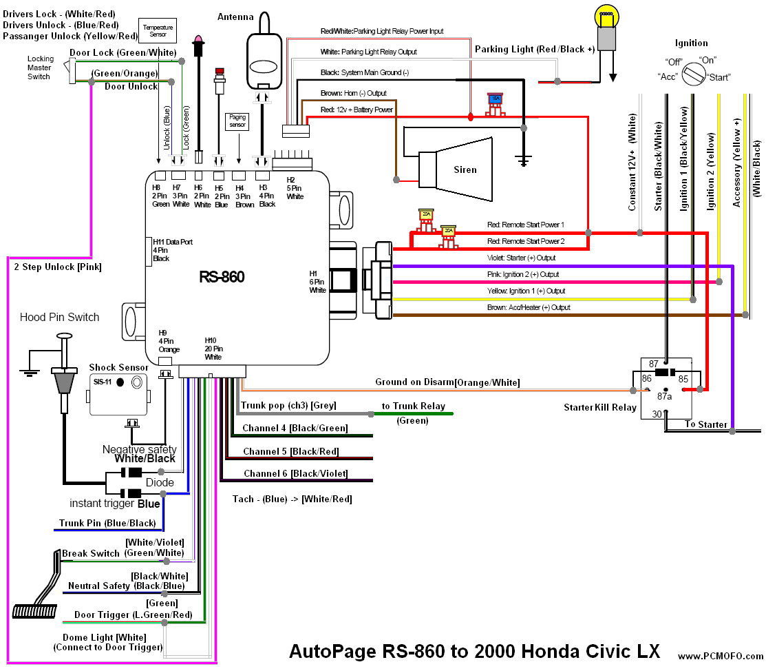
OK so my unit still isnt here yet :-( but I am sure it will arrive sometime this week. Anyway I was able to get into the autopage dealers section of the web site (pass:autopage )lol and download a nicer version of the instruction manual. I then decided the best thing I could do is to draw a diagram of the connections of wire colors between my car and the unit now before I connect them and it will make everything go smoother because I can double check my work now instead of when I am stuffed under my dash. Anyway here is the hookup diagram I made... I have a few places that tripped me up... I labeled them with a big red ? and a number so you know what part I am refering to...
2000 honda civic, autopage 860 -- posted image.
OK ? 1. top right.
The 2000 honda civic chart I downloaded from here says that Accessory is a yellow + wire. Another diagram has told me it is a WHITE/ black wire... which is true? (I am going to test all of the wires regardless to verify each one of course but like I said its nice to know ahead of time)
?2 top left.
The pink wire is set to output a double pulse to unlock all of the doors. My civic wireing diagram shows a lock/unlock and a passanger unlock. I assume that the pink double pulse wire goes to the same door unlock as the blue unlock wire and does not get connected to the passenger unlock wire... but why would it be in the diagram then if no one used it? Any thoughts on which is correct to use?
?3 bottom left
According to the instructions the hood pin needs to trigger both the instant blue trigger and negative safety wires and that they need to be isolated from eachother with a diode. Also the trunk pin needs to be connected to the instant trigger. This way if the trunk opens the car alarms but does not shut off and if the hood is opened the car shuts off and alarms. Is this connection correct?
?4 bottom right
This is a copy of the connection for a starter kill relay that I got from the instruction manual. I have attempted to simplify it and make it less confusing yet still work. Is it connected correctly?
Thats about it.. I might use one of the extra 3 channels to latch on or off a relay connected to my computer turn on wire in my car if I wanted to just turn on my car. The computer turns on the amps. If music starts playing though and the system is armed I would assume that it would set off the system?
Anything else fun I can do with the extra outputs?
Thanks for your help guys
pcmofo 
Member - Posts: 9
Member spacespace
Joined: October 29, 2006
Location: United States
Posted: November 06, 2006 at 1:47 AM / IP Logged  
ok so I added a 5th ?...
I want the dome light to function. The connection diagram for the civic says " connect to door trigger " so would this be correct? Would tripping the dome light somehow cause the alarm system to think that someone opened the car door and set the alarm off?
quarky42 
Member - Posts: 5
Member spacespace
Joined: October 28, 2006
Location: United States
Posted: November 06, 2006 at 5:06 PM / IP Logged  
1. Test to be sure. Sounds like you already know that.
2. I'm confused. Is your lock a single or double pulse to lock/unlock?    when I read that section of the manual it sounded to me like the middle (red) wire just not used and the green and blue wires are used instead to lock and unlock the doors...   hooked up one way they ground the switch/door relay to lock it and hooked up in another way they apply 12v to the door/switch/lock to lock it... just depends on which way your doors lock.
3. That looks correct to me. The two diodes are in place to keep voltage/current from one circuit flowing into the other part of the circuit... It "enforces" the path to ground.
4. I believe so...just double check the diode protected relay one more time to make sure that the diode is in the correct "direction". I don't have my file here for my alarm system otherwise I would just look it up. The direction of the diode protects the circuit that the relay is connected to from the electromagnetic pulse that is created when the relay turns off.
5. I don't think that is right but I have to go now, no time to try and figure out what that was for. Will try to look later. Email if I forget to check the forums.
tcn (put an at sign here) usa.com
pcmofo 
Member - Posts: 9
Member spacespace
Joined: October 29, 2006
Location: United States
Posted: November 07, 2006 at 12:22 PM / IP Logged  
I am fairly certian I have taken care of questions 1-3. 1 I can figre out, 2 is connected to the drivers unlock I believe no the passanger unlock and will just throw twice. and 3 should be correct.
As for ? 4 I have it connected to the ignition 1 wire but I think that it would be better if the relay interupted the starter line instead. Their is an example of this in the manual but they use the ground when armed to trigger the relay which I think is silly because if someone cuts power to the relay then it will complete the circuit. It makes more sense to require power ( ground on disarm) to complete the starter wire circuit so I think I will just wire it like that and it will be fine... I will wire the starter disable last to make sure that everything else is working first lol
So the only thing I have yet to truly figure out is how the dome light is supposed to be connected to my car!... Maybe it doesnt need to be connected at all? When I press the unlock or lock button on my current keyless entry remote (OEM) it turns the light on and off respectivly. So if the alarm system mearly triggered these lines would it be safe to assume that the dome light will follow suit? Again I can just not connect it and watch what happens but assuming the dome light does not turn on where should it be connected?
My system should be here by thursday evening so I plan on installing everything on friday, Just have to get some diodes etc and finish this diagram and I will be good to go.
alpinehead 
Member - Posts: 9
Member spacespace
Joined: November 07, 2006
Location: United States
Posted: November 07, 2006 at 9:31 PM / IP Logged  

hey

went to the autopage site....

but how did you do the wiring to your car.....is that custom?

or do they have diagrams for other cars also....

need a diagram for a 1987 765ti   760 volvo turbo wagon

thanks for the info!
pcmofo 
Member - Posts: 9
Member spacespace
Joined: October 29, 2006
Location: United States
Posted: November 07, 2006 at 11:30 PM / IP Logged  
I got the wireing diagram from here then just made my own picture of which wire to connect between my car and the autopage unit and color coded it as a master sheet to use on my install... it gets confusing looking at 2 sheets and compairing them... I would otherwise mix up BLACK/ blue and blue/black or somtehing like that...
This gives me a chance to double check my work
Page of 2

  Printable version Printable version Post ReplyPost New Topic
You cannot post new topics in this forum
You cannot reply to topics in this forum
You cannot delete your posts in this forum
You cannot edit your posts in this forum
You cannot create polls in this forum
You cannot vote in polls in this forum

  •  
Search the12volt.com
Follow the12volt.com Follow the12volt.com on Facebook
Friday, May 10, 2024 • Copyright © 1999-2024 the12volt.com, All Rights Reserved Privacy Policy & Use of Cookies
Disclaimer: *All information on this site ( the12volt.com ) is provided "as is" without any warranty of any kind, either expressed or implied, including but not limited to fitness for a particular use. Any user assumes the entire risk as to the accuracy and use of this information. Please verify all wire colors and diagrams before applying any information.

Secured by Sectigo
the12volt.com spacer
Support the12volt.com
Top
the12volt.com spacer