the12volt.com spacer
icon

Adding switch to control non-oe acutators


Post ReplyPost New Topic
< Prev Topic Next Topic >
steveo200077 
Member - Posts: 5
Member spacespace
Joined: July 28, 2006
Location: United States
Posted: December 10, 2006 at 4:04 PM / IP Logged  
OK I have searched all over the place and the only thing that did was make me confused. This is what im trying to do I have a 2002 cavalier that did NOT come with power locks. I added dei 524t 2 wire acutator. Also I have them hooked to a autopage rf-520lcd. this unit has built in door lock/unlock relays. I Want to add a switch to control the locks The alarm has 5 wires on a "door lock/unlock" harness.
The wires are
BROWN unlock switch.....N/C(87a)
Light blue UN-Lock motor...common (30)
Violet unlock... N\O (87)
White Lock Switch...N\C (87a)
Light green lock motor ...common(30)
Violet/red lock....N\O (87)
The violet and violet red are connected to 12v+
right now the white and brown are grounded.
Here is what im thinking the white wire goes to one side of a switch. the brown goes to other side of the switch With a ground in the middle. do i need any relays since they are already built in?
Thankyou
ringojam 
Copper - Posts: 215
Copper spacespace
Joined: June 10, 2003
Location: Manitoba, Jamaica
Posted: December 10, 2006 at 6:54 PM / IP Logged  
Use a spdt switch connect the center pole of the switch to ground  and the other side  to the brown and white wire on a 5 wire acuator in the drivers door,sorry but you will need to change acuator in the drivers door to 5 wire.
Jamaica home of the worlds fastest man.
tech2uned 
Member - Posts: 5
Member spacespace
Joined: December 10, 2006
Location: United States
Posted: December 10, 2006 at 8:54 PM / IP Logged  

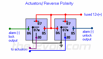
Does the alarm have outputs for doorlocks? If so, the easiest way would be to ignore the built in relays. Just get 2 new relays, and wire them up as if you didnt have that alarm that had built in relays. Now run 2 wires to wherever your switch will be, and connect those to a spdt switch(like how the above poster stated). On the other end of those wires, connect them to terminals 85 and 86(see the diagram)

Adding switch to control non-oe acutators -- posted image.


Sorry, you can NOT post a reply.
This topic is closed.

  Printable version Printable version Post ReplyPost New Topic
You cannot post new topics in this forum
You cannot reply to topics in this forum
You cannot delete your posts in this forum
You cannot edit your posts in this forum
You cannot create polls in this forum
You cannot vote in polls in this forum

  •  
Search the12volt.com
Follow the12volt.com Follow the12volt.com on Facebook
Friday, May 3, 2024 • Copyright © 1999-2024 the12volt.com, All Rights Reserved Privacy Policy & Use of Cookies
Disclaimer: *All information on this site ( the12volt.com ) is provided "as is" without any warranty of any kind, either expressed or implied, including but not limited to fitness for a particular use. Any user assumes the entire risk as to the accuracy and use of this information. Please verify all wire colors and diagrams before applying any information.

Secured by Sectigo
the12volt.com spacer
Support the12volt.com
Top
the12volt.com spacer