the12volt.com spacer
icon

keyless entry, 93 Mustang


Post ReplyPost New Topic
< Prev Topic Next Topic >
mikiedoo 
Member - Posts: 12
Member spacespace
Joined: January 03, 2007
Location: United States
Posted: January 03, 2007 at 2:56 PM / IP Logged  

Hi guys,

I have a problem thats stumping me and need your expretice. I own a 93 Mustang and just purchased an aftermarket keyless entry setup. I have already wired a relay for the trunk pop and parking light flash. I got to the door locks / unlocks and have run into a wall. My brain does not have relays so I am using 2 spdt relays. I have been told by one person to wire them up 5 wire reversal and one person said 5 wire alternating. I need someone to plainly tell me what wire goes where before I pull out my hair...lol Also I think I found the right door wires in the kick panel. I have a pink with yellow stripe to lock and a pink with green stripe to unlock.

Also how do I know which side of the wire is the motor side and which side is the switch side? since both the motor and the switch are located in the door and Im up in the kick panel passed all of that. 

I tried the search feature , but need someone to be very specific in their discription so I made a new thread.

Thank  anyone who can help.

Mike

1993 Mustang 5.0 LX
Hymer 
Silver - Posts: 695
Silver spacespace
Joined: November 20, 2004
Location: United States
Posted: January 03, 2007 at 3:21 PM / IP Logged  
It is a 5 wire reverse setup. Pink/yell pink/green I know there is a relay setup on this site for that. Any way relay 1 86 (-) trigger from keyless, 87 - 85 12v , 87a switch side of unlock wire (cut this wire) , 30 actuator side of unlock wire... Relay 2 86-87 12v, 87a switch side of lock wire (again cut this wire) 30 actuator side of lock wire, 85 (-) lock trigger from keyless...
Tire Proz Stillwater Mn
High End Restyling and Comlete Repair
mikiedoo 
Member - Posts: 12
Member spacespace
Joined: January 03, 2007
Location: United States
Posted: January 03, 2007 at 4:09 PM / IP Logged  

Ok great.

Now the only other question I have is how do you split the wires between the actuator motor and the actuator switch in the kick panel. You would think that the switch and motor are both further down the line ( in the door ) than where I am tapping in.

Im probably just not visualizing the wires and they may go from the motor up into the kick panel to wherever, then go back into the door to the switch.

If I get these wires backward ( switch and motor ) will I burn anything up?

Thank you so much for the info. Friday I am going to finish up the job and am trying to get all of the information before then.

Mike

1993 Mustang 5.0 LX
Hymer 
Silver - Posts: 695
Silver spacespace
Joined: November 20, 2004
Location: United States
Posted: January 03, 2007 at 5:08 PM / IP Logged  
It's been a while since I did them, but when you cut the wire, the switch side will have nothing on it. when you hit the switch it should read 12v or ground..    If you miss wire it, I dont think youll burn anything up, but the locks wont function or operate backwards...   If Im wrong someone will chime in....
Tire Proz Stillwater Mn
High End Restyling and Comlete Repair
KarTuneMan 
Platinum - Posts: 7,056
Platinum spaceThis member has made a donation to the12volt.com. Click here for more info.spaceThis member consistently provides reliable informationspace
Joined: December 14, 2004
Location: Isle Of Man
Posted: January 04, 2007 at 8:56 AM / IP Logged  
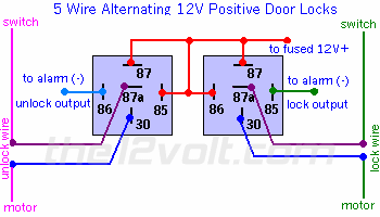
keyless entry, 93 Mustang -- posted image.
mikiedoo 
Member - Posts: 12
Member spacespace
Joined: January 03, 2007
Location: United States
Posted: January 04, 2007 at 7:11 PM / IP Logged  

So the diagram above is a 5 wire alternating positive ?

I was under the impression that was different that a 5 wire reverse and negative polarity?

I am installing tomorrow and will go with the above.

Thanks

1993 Mustang 5.0 LX
JWorm 
Platinum - Posts: 2,208
Platinum spacespace
Joined: December 11, 2002
Location: New Hampshire, United States
Posted: January 04, 2007 at 7:21 PM / IP Logged  
There are many names for 5-wire doorlocks. The above diagram is the correct diagram...no matter what you want to call it.
Use your multimeter to determine the correct lock and unlock wires. When you press the switch on the door, the meter will jump to about 12 volts on the corresponding wire.
To determine 'motor' and 'switch' side....
Take the lock wire....cut it. Put your black meter lead to ground....and the red meter lead to one end of the wire you just cut. Hold lock on the drivers door. The locks shouldn't move. If you are on the 'switch side' of the wire your meter will read 12v. If you are on the 'motor side'...your meter will read around 0v. Attach the cut lock wire to the corresponding location of the relay.
For unlock...repeat the above using the unlock wire, and the unlock part of the switch.
Do not have both the unlock and lock wire cut at the same time. Things won't meter properly if you do.
mikiedoo 
Member - Posts: 12
Member spacespace
Joined: January 03, 2007
Location: United States
Posted: January 04, 2007 at 7:47 PM / IP Logged  
Thank you ... So much...All of you guys.
1993 Mustang 5.0 LX
mikiedoo 
Member - Posts: 12
Member spacespace
Joined: January 03, 2007
Location: United States
Posted: January 05, 2007 at 11:32 AM / IP Logged  

It worked like a charm. !

Thanks again for all of your valuable knowledge.

Mike

1993 Mustang 5.0 LX

Sorry, you can NOT post a reply.
This topic is closed.

  Printable version Printable version Post ReplyPost New Topic
You cannot post new topics in this forum
You cannot reply to topics in this forum
You cannot delete your posts in this forum
You cannot edit your posts in this forum
You cannot create polls in this forum
You cannot vote in polls in this forum

  •  
Search the12volt.com
Follow the12volt.com Follow the12volt.com on Facebook
Monday, May 13, 2024 • Copyright © 1999-2024 the12volt.com, All Rights Reserved Privacy Policy & Use of Cookies
Disclaimer: *All information on this site ( the12volt.com ) is provided "as is" without any warranty of any kind, either expressed or implied, including but not limited to fitness for a particular use. Any user assumes the entire risk as to the accuracy and use of this information. Please verify all wire colors and diagrams before applying any information.

Secured by Sectigo
the12volt.com spacer
Support the12volt.com
Top
the12volt.com spacer