the12volt.com spacer
icon

2002 F250, 5 Wire Locks, 451M


Post ReplyPost New Topic
< Prev Topic Next Topic >
tbird2340 
Copper - Posts: 363
Copper spacespace
Joined: October 03, 2003
Location: Ohio, United States
Posted: January 15, 2007 at 10:06 AM / IP Logged  
Would someone be able to tell me how to hook up a 451M with the 5 wire configuration? I don't have a set of directions for them and I'm doing a 02 F250 which I think has the 5 wire locks.
Much appreciated.
Thanks
KarTuneMan 
Platinum - Posts: 7,056
Platinum spaceThis member has made a donation to the12volt.com. Click here for more info.spaceThis member consistently provides reliable informationspace
Joined: December 14, 2004
Location: Isle Of Man
Posted: January 15, 2007 at 10:20 AM / IP Logged  

I asume your rig had NO factory keyless....correct?

LOCK WHITE/ red In harness above gas pedal   + 
 On 4 door models, these wire are negative trigger. Vehicles with no keyless entry, colors are Pink / YELLOW for lock and Pink/green for unlock in 5-wire reverse polarity. They will be found in either kickpanel.
 UNLOCK BLACK/ white In harness above gas pedal   + 
 On 4 door models, these wire are negative trigger. Vehicles with no keyless entry, colors are Pink / YELLOW for lock and Pink/green for unlock in 5-wire reverse polarity. They will be found in either kickpanel.

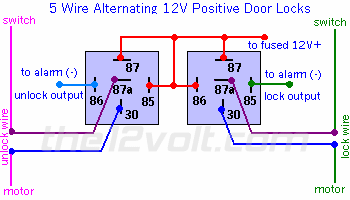
Wire your relays like this....

2002 F250, 5 Wire Locks, 451M -- posted image.
tbird2340 
Copper - Posts: 363
Copper spacespace
Joined: October 03, 2003
Location: Ohio, United States
Posted: January 15, 2007 at 11:22 AM / IP Logged  
KarTuneMan wrote:

I asume your rig had NO factory keyless....correct?

It has power locks but no keyfobs. I'm not 100% how the locks are yet as I'm picking it up in about an hour..
Would you happen to know how to wire it via a 451M module?
Thanks for the help.
profuse007 
Gold - Posts: 2,015
Gold spacespace
Joined: October 20, 2002
Location: Texas, United States
Posted: January 15, 2007 at 12:29 PM / IP Logged  
the 451m has two relays in there. so use the diagram listed above.
here is a little relay reference you can use:
30 pin is Common
87 pin is Normally Open
87a pin is Normally Closed
green and blue wire is lock and unlock.
If you put up the exact diagram thats posted on the back of the 451m, someone here will pin point it out one by one. Above should give you enough infos to figure it out.
Houston,TX
"The two most common elements in the universe are H+ and stupidity" (Ellison).
tbird2340 
Copper - Posts: 363
Copper spacespace
Joined: October 03, 2003
Location: Ohio, United States
Posted: January 15, 2007 at 1:22 PM / IP Logged  
451M Wiring:
PURPLE / Black Pin 87 Lock/Unlock Normally Open
GREEN/ Black Pin 30 Lock Output
WHITE/ Black 87A Lock Normally Closed
Blue/Black Pin 30 Unlock Output
BROWN / Black Pin 87A Unlock Normally Closed
Thanks!!
profuse007 
Gold - Posts: 2,015
Gold spacespace
Joined: October 20, 2002
Location: Texas, United States
Posted: January 15, 2007 at 1:40 PM / IP Logged  
PURPLE / Black Pin 87 Lock/Unlock Normally Open-> +12v fused
cut lock wire
GREEN/ Black Pin 30 Lock Output->motor side of cut lock wire
WHITE/ Black 87A Lock Normally Closed->switch side
cut unlk wire
Blue/Black Pin 30 Unlock Output->motor side
BROWN / Black Pin 87A Unlock Normally Closed->switch side
Houston,TX
"The two most common elements in the universe are H+ and stupidity" (Ellison).
tbird2340 
Copper - Posts: 363
Copper spacespace
Joined: October 03, 2003
Location: Ohio, United States
Posted: January 15, 2007 at 2:03 PM / IP Logged  
Thanks a lot. Is there a test to be 100% which side is going to the motor and which is going to the switch?
tbird2340 
Copper - Posts: 363
Copper spacespace
Joined: October 03, 2003
Location: Ohio, United States
Posted: January 15, 2007 at 3:53 PM / IP Logged  
Well I just guessed and guessed right.
All done works great. Thanks for the help!

Sorry, you can NOT post a reply.
This topic is closed.

  Printable version Printable version Post ReplyPost New Topic
You cannot post new topics in this forum
You cannot reply to topics in this forum
You cannot delete your posts in this forum
You cannot edit your posts in this forum
You cannot create polls in this forum
You cannot vote in polls in this forum

  •  
Search the12volt.com
Follow the12volt.com Follow the12volt.com on Facebook
Sunday, April 28, 2024 • Copyright © 1999-2024 the12volt.com, All Rights Reserved Privacy Policy & Use of Cookies
Disclaimer: *All information on this site ( the12volt.com ) is provided "as is" without any warranty of any kind, either expressed or implied, including but not limited to fitness for a particular use. Any user assumes the entire risk as to the accuracy and use of this information. Please verify all wire colors and diagrams before applying any information.

Secured by Sectigo
the12volt.com spacer
Support the12volt.com
Top
the12volt.com spacer