the12volt.com spacer
icon

2001 s10, xplore alarm starter


Post ReplyPost New Topic
< Prev Topic Next Topic >
r_mittendorf 
Member - Posts: 5
Member spacespace
Joined: January 26, 2007
Location: United States
Posted: January 29, 2007 at 5:22 PM / IP Logged  
where is the alternator wire located inside the cab that has a 12volt output when the engine is running?
the diagram shows a wire going to the positive door trigger and one to the negative door trigger. i am confused on what they consider a door trigger. If it is the door plunger, then it is a wire completing the ground, why does it call for a positive and a negative connection. The truck has manual locks.
When remote starting the truck, on the first try it begins to run for a few seconds and quits like it is starved for fuel.
ghost
rudydapimp 
Copper - Posts: 390
Copper spacespace
Joined: February 27, 2006
Location: United States
Posted: January 29, 2007 at 7:24 PM / IP Logged  
Tach wire is White, (ac current) at the coil on pass side, top of engine. You only need one of the triggers, all door trigger is white (-) at courtesy light,or at the BCM, next to gas pedal, tan is drivers side and orange is pass side, use and diode isolate each.
The reason it wont run for longer than 3 seconds is my guess is you didnt get a passlock II interface. DEI part number 555LW or go to bypasskits.com
r_mittendorf 
Member - Posts: 5
Member spacespace
Joined: January 26, 2007
Location: United States
Posted: January 30, 2007 at 1:42 PM / IP Logged  
I now have a 457G GM DATA BUS Interface (says it will work in place of a pass lock II interface. THe diagram shows a wire from the Interface to a wire that goes to ground when running....I can not find a wire coming from the xplore unit that goes to ground when running... can anyone tell me where to find this connection?
ghost
Twelvoltz 
Platinum - Posts: 2,384
Platinum spaceThis member has made a donation to the12volt.com. Click here for more info.spaceThis member consistently provides reliable informationspace
Joined: March 24, 2005
Location: New Jersey, United States
Posted: January 30, 2007 at 2:22 PM / IP Logged  
Does your Xplore unit offer a negative third ignition output or a wire that is labeled status output?
r_mittendorf 
Member - Posts: 5
Member spacespace
Joined: January 26, 2007
Location: United States
Posted: January 30, 2007 at 3:42 PM / IP Logged  
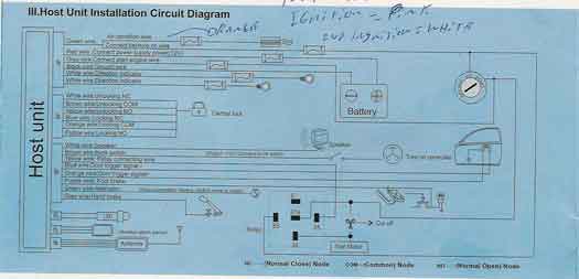
2001 s10, xplore alarm starter -- posted image.
only wire I see that might be suspect would be the one labled "relay connecting wire"
ghost
r_mittendorf 
Member - Posts: 5
Member spacespace
Joined: January 26, 2007
Location: United States
Posted: January 30, 2007 at 3:55 PM / IP Logged  
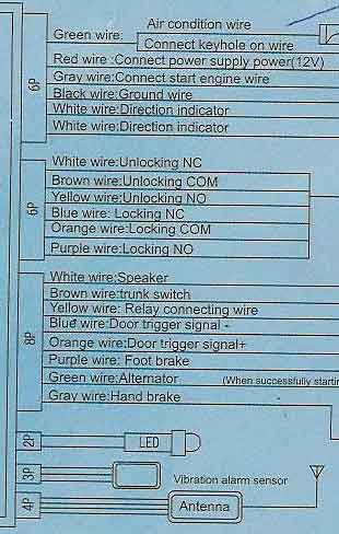
2001 s10, xplore alarm starter -- posted image.
This diagram only shows the wires at the unit but is easier to read.
ghost
r_mittendorf 
Member - Posts: 5
Member spacespace
Joined: January 26, 2007
Location: United States
Posted: January 31, 2007 at 5:12 PM / IP Logged  
Problem solved:
The wire from the 457G Gm data interface that needed to go to a connection that read ground when engine was running...Used the wire from the Xplore module that went to the accessory line and jumped a wire over to a relay that I rigged to ground when the accessory line went positive.
The line from the xplore that needed a line that read pos while the engine was running: ran that line to the small red wire that came off the back of the alternator.
There were two door trigger wires coming from the Xplore unit. (-) (+). I used the (-) and wired to the tan wire and the purple wire located in the harness just to the side of the gas pedal. (used a diode on each line to prevent current from crossing back and forth between the purple and tan lines.
ghost

Sorry, you can NOT post a reply.
This topic is closed.

  Printable version Printable version Post ReplyPost New Topic
You cannot post new topics in this forum
You cannot reply to topics in this forum
You cannot delete your posts in this forum
You cannot edit your posts in this forum
You cannot create polls in this forum
You cannot vote in polls in this forum

  •  
Search the12volt.com
Follow the12volt.com Follow the12volt.com on Facebook
Friday, May 17, 2024 • Copyright © 1999-2024 the12volt.com, All Rights Reserved Privacy Policy & Use of Cookies
Disclaimer: *All information on this site ( the12volt.com ) is provided "as is" without any warranty of any kind, either expressed or implied, including but not limited to fitness for a particular use. Any user assumes the entire risk as to the accuracy and use of this information. Please verify all wire colors and diagrams before applying any information.

Secured by Sectigo
the12volt.com spacer
Support the12volt.com
Top
the12volt.com spacer