the12volt.com spacer
icon

keyless entry wiring 89 corvette


Post ReplyPost New Topic
< Prev Topic Next Topic >
danspeed1 
Member - Posts: 47
Member spacespace
Joined: April 09, 2007
Location: United States
Posted: July 29, 2007 at 5:00 PM / IP Logged  

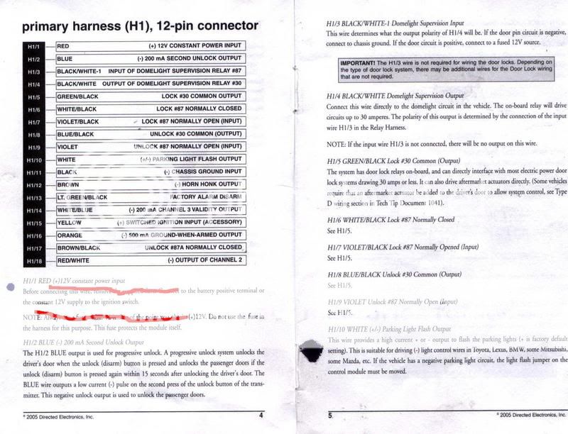
I am having a lot of trouble installing a Viper VKE1000 Keyless entry system into my 89 Corvette.  Well I've gotten into that part of the project where the easy wires are done and the confusion begins.  If any of you know where to connect these wires to, let me know???  :confused: I am confused about the setup, don't have the proper wiring diagrams I need, and I have to get the car back on the road in a timely manor.  I did it again, backed myself into a corner.  Take a look....

[IMG]https://i142.photobucket.com/albums/r97/BG528/diagram1.jpg[/IMG]

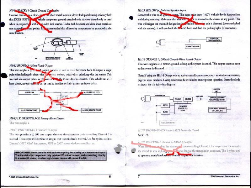
[IMG]https://i142.photobucket.com/albums/r97/BG528/diagram2.jpg[/IMG]
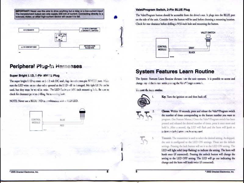
[IMG]https://i142.photobucket.com/albums/r97/BG528/diagram3.jpg[/IMG]

Above with red X's are the steps I already taken.

Problems I had because of lack of diagram....

1.  I found the door Lock and Unlock wire on the drivers side harness.  First off, is an 89 vette capable of "Progressive Unlock?"  Meaning, on the first click only the drivers door unlocks and then clicking the button again unlocks the passenger door.  Seems to me this is not a possible function.  When I hit the switch inside the car, it locks and unlock both doors. 

[b]Which wires in this diagram would you send to the two wires that control the lock and unlock function. [/b] 

2.  If you look at the diagrams you will notice there are 5 lock/unlock, inputs, outputs, and normals?  Why so many wires, what do they do, how do I hook this up?  

What the heck are Dome light supervision outputs and how do I wire those up?

I need to get myself out of this mess, any help is appreciated.

DG

1971 Chevelle SS
1989 Corvette
1996 Impala SS
danspeed1 
Member - Posts: 47
Member spacespace
Joined: April 09, 2007
Location: United States
Posted: July 29, 2007 at 5:01 PM / IP Logged  
keyless entry wiring 89 corvette -- posted image.
1971 Chevelle SS
1989 Corvette
1996 Impala SS
fkelsey 
Copper - Posts: 94
Copper spacespace
Joined: March 16, 2007
Posted: July 29, 2007 at 7:46 PM / IP Logged  
Well as I read it lock is light blue and unlock is black in your vette and they are five wire. So here is what you do check the wires you found with your dmm and make sure they show 12 volts when triggered. Cut both the wires in two separating them into a switch and a motor side. Use your dmm and check both sides of the wire which ever side shows 12 volts when you depress the switch is you guessed it the switch side. Violet/Black H1/7 and Violet H1/9 go to 12 volts constant. WHITE/ Black H1/6 goes to the lock switch and GREEN/ Black H1/5 goes to the lock motor (this is your already cut in two light blu wire. BROWN / Black H 1/17 goes to unlock switch and Blue/Black H 1/8 goes to the unlock motor (your already cut in two black wire.
fkelsey 
Copper - Posts: 94
Copper spacespace
Joined: March 16, 2007
Posted: July 29, 2007 at 7:58 PM / IP Logged  
The reason for so many wires is the unit has built in relays for cars such as yours. If it was not the way it was you would have to build external SPDT relays to lock and unlock your doors. Viper truly is quality equipment and they usually think of everything to make an install easier. As for dome light supervision that is for turning your domelight on when you unlock your door. The negative door trigger (white wire at the under dash light) is the wire you use for this. Ground H 1/3, hook H 1/4 to this white wire. Check the white wire at the bulb under your dash with your dmm and make sure it is negative though. It shows negative on directechs but always check.
danspeed1 
Member - Posts: 47
Member spacespace
Joined: April 09, 2007
Location: United States
Posted: July 29, 2007 at 8:19 PM / IP Logged  

fkelsey wrote:
The reason for so many wires is the unit has built in relays for cars such as yours. If it was not the way it was you would have to build external SPDT relays to lock and unlock your doors. Viper truly is quality equipment and they usually think of everything to make an install easier. As for dome light supervision that is for turning your domelight on when you unlock your door. The negative door trigger (white wire at the under dash light) is the wire you use for this. Ground H 1/3, hook H 1/4 to this white wire. Check the white wire at the bulb under your dash with your dmm and make sure it is negative though. It shows negative on directechs but always check.

Hey FKelsey, thanks for taking a swing at this problem.  I have been working on this all day and I can't seem to get anything accomplished.  One more question for you, on the one wiring diagram I have from Viper it shows the corvette having a door lock master being the passenger side.  Does this make any sort of difference, or can it be wired from either side?

DG

1971 Chevelle SS
1989 Corvette
1996 Impala SS
fkelsey 
Copper - Posts: 94
Copper spacespace
Joined: March 16, 2007
Posted: July 29, 2007 at 8:26 PM / IP Logged  
It can be wired in either kick panel but when you check your switch and motor side using your passenger switch. Good luck and holler if you need anything else.
danspeed1 
Member - Posts: 47
Member spacespace
Joined: April 09, 2007
Location: United States
Posted: July 30, 2007 at 3:51 PM / IP Logged  

fkelsey wrote:
It can be wired in either kick panel but when you check your switch and motor side using your passenger switch. Good luck and holler if you need anything else.

Hey Fkelsey,

You were right, thanks alot for the help.  It still took me a while to get it right but i finally got it.  This car is 18 years old and this is not the first alarm that has been installed.  The wiring harness was hacked to pieces and I had a few other wiring issues i had to straighten out. 

Well anyway, I do have one more favor to ask... Down to the last two wires of the VKE1000 setup. I am down to connecting up the orange wire H1/16 -500ma Ground-when armed output, and the GREEN/ black factory arm disarm. I know i am going to need to insert a relay somewhere inbetween this setup to make sure the factory alarm turns off when the doors are opened with a remote. If anyone could explain which wire goes where (so a child could understand it, it would be greatly appreciated. 

Thanks again Fkelsey,

Dan

1971 Chevelle SS
1989 Corvette
1996 Impala SS
fkelsey 
Copper - Posts: 94
Copper spacespace
Joined: March 16, 2007
Posted: July 30, 2007 at 5:22 PM / IP Logged  
Let me ask this for the grounded when armed wire are you hooking up a starter kill relay? That is usually what that wire is for or to activate an external sensor like a motion, microwave or enviroment etcc. etc. If you are not doing a starter kill just cap it off if you are just go to the relay page and look up starter kill relays and that will hook you up. For your factory disarm it says it is light green (negative) in either kick panel. Just hook your meter to a light green wire in the panel and use your key to unlock the door with the key cylinder and it should show a momentary negative voltage. Once you found that wire hook your GREEN/ black wire to that bad boy and off you go.
danspeed1 
Member - Posts: 47
Member spacespace
Joined: April 09, 2007
Location: United States
Posted: July 30, 2007 at 5:49 PM / IP Logged  

fkelsey wrote:
Let me ask this for the grounded when armed wire are you hooking up a starter kill relay? That is usually what that wire is for or to activate an external sensor like a motion, microwave or enviroment etcc. etc. If you are not doing a starter kill just cap it off if you are just go to the relay page and look up starter kill relays and that will hook you up. For your factory disarm it says it is light green (negative) in either kick panel. Just hook your meter to a light green wire in the panel and use your key to unlock the door with the key cylinder and it should show a momentary negative voltage. Once you found that wire hook your GREEN/ black wire to that bad boy and off you go.

If the starter kill relay is an option, I would like to include it. 

I feel like I need to install a relay in between the starter wire and then use the orange one to trigger it but that would have a reverse effect on what I am looking to do.  the car would only start when the alarm is triggered.  How do I wire the starter kill up so that only when the alarm goes off it kills the starter?

Also, if you could take a look at this site I found,.... http://www.batee.com/corvette/index.shtml  it says I need to insert a relay for the theft deterrent system.  The only problem is I can't understand the awful diagrams he made.  Do you make anything of this?

Thanks again,

Dan

1971 Chevelle SS
1989 Corvette
1996 Impala SS
fkelsey 
Copper - Posts: 94
Copper spacespace
Joined: March 16, 2007
Posted: July 30, 2007 at 6:11 PM / IP Logged  
Holy S@!t no freaking wonder you are confused what a bunch of garbage. Okay here we go, for your disarm, take a realay 85 12 volts, 87 ground, 85 geen/black from alarm, 30 to your light green wire in your car. For your starter kill hook 86 to 12 volts ignition, 85 to grounded when armed cut your yellow starter wire in half and hook the switch side to 87a and starter side to 30. Go here https://www.the12volt.com/relays/page2.asp
Page of 2

  Printable version Printable version Post ReplyPost New Topic
You cannot post new topics in this forum
You cannot reply to topics in this forum
You cannot delete your posts in this forum
You cannot edit your posts in this forum
You cannot create polls in this forum
You cannot vote in polls in this forum

  •  
Search the12volt.com
Follow the12volt.com Follow the12volt.com on Facebook
Sunday, April 28, 2024 • Copyright © 1999-2024 the12volt.com, All Rights Reserved Privacy Policy & Use of Cookies
Disclaimer: *All information on this site ( the12volt.com ) is provided "as is" without any warranty of any kind, either expressed or implied, including but not limited to fitness for a particular use. Any user assumes the entire risk as to the accuracy and use of this information. Please verify all wire colors and diagrams before applying any information.

Secured by Sectigo
the12volt.com spacer
Support the12volt.com
Top
the12volt.com spacer