the12volt.com spacer
icon

door lock/unlock wires 2003 f250


Post ReplyPost New Topic
< Prev Topic Next Topic >
dustindiesel 
Member - Posts: 9
Member spacespace
Joined: October 19, 2007
Location: Florida, United States
Posted: October 25, 2007 at 8:06 AM / IP Logged  

hey guys,i have a 2003 f250 diesel 6.0l and i am installing the code ca-670 alarm.i got most everything done except im lost on the door locks. my truck has keyless entry already and i found the blk/wht and wht/red wires that read pos 12v when locked/ unlocked but i cant seem to get the wires hooked up right to work??

thanks for the help:)

KarTuneMan 
Platinum - Posts: 7,056
Platinum spaceThis member has made a donation to the12volt.com. Click here for more info.spaceThis member consistently provides reliable informationspace
Joined: December 14, 2004
Location: Isle Of Man
Posted: October 25, 2007 at 8:22 AM / IP Logged  

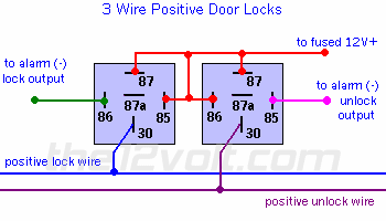
How did you "try" and wire them? They are simple neagative trigger. You could wire them like so

Change the pin 87 to ground......     

door lock/unlock wires 2003 f250 -- posted image.
dustindiesel 
Member - Posts: 9
Member spacespace
Joined: October 19, 2007
Location: Florida, United States
Posted: October 25, 2007 at 8:29 AM / IP Logged  

sry i just was getting a little confused this being my first alarm im installing...

so if i run the pin 87 to ground and run the pin85 on the one relay and pin 86 on the other relay to 12v and hook up the rest accordingly it would do it?? thanks for the help i really appreciate it..

Twelvoltz 
Platinum - Posts: 2,384
Platinum spaceThis member has made a donation to the12volt.com. Click here for more info.spaceThis member consistently provides reliable informationspace
Joined: March 24, 2005
Location: New Jersey, United States
Posted: October 25, 2007 at 8:51 AM / IP Logged  
Your code alarm system has negative outputs for door locks...should not need the relay setup.
Just solder the green to your lock wire and blue to your unlock wire.
Installer, IT support, and FFL. I need less hobbies.
dustindiesel 
Member - Posts: 9
Member spacespace
Joined: October 19, 2007
Location: Florida, United States
Posted: October 25, 2007 at 9:32 AM / IP Logged  

thanks. my problem exists b/c the outputs.

coming from the alarm box --the green wire sees ground when locked and is 12v at rest(works ok),the blue wire sees 12v when locked and rests at ground when locked(wth??),and the blue/grn wire sees grnd when unlocked is pressed twice for two stage feature.

so i hooked the 2 stage wire up which will work fine i jus gotta press the unlock 2x to get in. i dunno whats up with the unlock output blue wire..everytime i hook it to any of the lock/unlock wires it activated them..is this a fault in the box itself??

thanks again yall

dustindiesel 
Member - Posts: 9
Member spacespace
Joined: October 19, 2007
Location: Florida, United States
Posted: October 25, 2007 at 9:36 AM / IP Logged  

sry had to EDIT.......read this one instead

dustindiesel wrote:

thanks. my problem exists b/c the outputs.

coming from the alarm box --the green wire sees ground when LOCKED and is 12v at rest(works ok),the blue wire sees 12v when LOCKED and rests at ground (wth??),and the blue/grn wire sees grnd when unlocked is pressed twice for two stage feature.

so i hooked the 2 stage wire up which will work fine i jus gotta press the unlock 2x to get in. i dunno whats up with the unlock output blue wire..everytime i hook it to any of the lock/unlock wires it activated them..is this a fault in the box itself?? the only wire that registers ground when pressed is the 2nd stage unlock..i think the blue wire is a lil screwey

thanks again yall

dustindiesel 
Member - Posts: 9
Member spacespace
Joined: October 19, 2007
Location: Florida, United States
Posted: October 25, 2007 at 8:46 PM / IP Logged  

so now that im done with the main hookups i want to try and get the optional outputs hooked up to run the windows up and down...

i imagine i can hook a relay to each corresponding wire that sends 12v to the mtr to go up and 12v to make it go down(thats what it is on my truck)..just so i get it right,can someone walk me through on how to hook up a circuit thats normally grounded-12v when on (up/down)  to a relay. my alarm sends out a neg output to activate the diff options so my thinkin is if i run a jumper wire to pin 30 from the window mtr, 12v to pin 87 and 86, then run the alarm neg output wire to pin 85 it will operate the up/down funct of the windows right???

thanks

dustin

Twelvoltz 
Platinum - Posts: 2,384
Platinum spaceThis member has made a donation to the12volt.com. Click here for more info.spaceThis member consistently provides reliable informationspace
Joined: March 24, 2005
Location: New Jersey, United States
Posted: October 26, 2007 at 7:01 AM / IP Logged  
Not really. Your thinking is correct with a couple of things missed.
1. You would need to run a +12V into the door to supply the motor with power. Or energize the accessory circuit that supplies the window motor while trying to roll it up.
2. You need to separate the other side of your wiring from ground otherwise you are just going to be sending +12V directly to ground. You would accomplish this by using a 5-wire setup on the roll up leg of the motor. Check this diagram it is for door locks but will give you the basic understanding of how to wire the relay.
3. If you are looking to hold the button down until the window rolls up you would need to be looking at the vehicle to keep the motor from burning up.
My suggestion...if you want to roll the windows up/down via the remote pick up a module designed to do that. The 530T is the module I recommend.
Installer, IT support, and FFL. I need less hobbies.

Sorry, you can NOT post a reply.
This topic is closed.

  Printable version Printable version Post ReplyPost New Topic
You cannot post new topics in this forum
You cannot reply to topics in this forum
You cannot delete your posts in this forum
You cannot edit your posts in this forum
You cannot create polls in this forum
You cannot vote in polls in this forum

  •  
Search the12volt.com
Follow the12volt.com Follow the12volt.com on Facebook
Thursday, May 2, 2024 • Copyright © 1999-2024 the12volt.com, All Rights Reserved Privacy Policy & Use of Cookies
Disclaimer: *All information on this site ( the12volt.com ) is provided "as is" without any warranty of any kind, either expressed or implied, including but not limited to fitness for a particular use. Any user assumes the entire risk as to the accuracy and use of this information. Please verify all wire colors and diagrams before applying any information.

Secured by Sectigo
the12volt.com spacer
Support the12volt.com
Top
the12volt.com spacer