the12volt.com spacer
icon

97 ford f 150 adding remote start


Post ReplyPost New Topic
< Prev Topic Next Topic >
mendozalester 
Member - Posts: 12
Member spacespace
Joined: February 17, 2006
Location: United States
Posted: October 28, 2007 at 3:44 AM / IP Logged  
Seeking help from experienced installers.  I added a Scytek 5000RS Alarm/Remote start to my 97 Ford F-150 and everything is working fine except for the AC, it is not blowing air when the truck is remote started.  This is my first remote start install and I want to know if I missed a step during the install.  From reading the forum looks like the accesory wires should be connected to something.  Thanks for any assistance and input.
KarTuneMan 
Platinum - Posts: 7,056
Platinum spaceThis member has made a donation to the12volt.com. Click here for more info.spaceThis member consistently provides reliable informationspace
Joined: December 14, 2004
Location: Isle Of Man
Posted: October 28, 2007 at 9:32 AM / IP Logged  
 12 VOLTS Yellow Ignition harness   + 
 IGNITION Blue/green Ignition harness   + 
 ACCESSORY Gray / YELLOW Ignition harness   + 
 ACCESSORY 2 RED / black & Blue/pink Ignition harness   + 
 This vehicle needs 3 accessories which must be connected with accessory or the ABS light will come on. ABS is controlled by the blue/pink. RED / black controls the a/c.
 Read thew fine print!
cderobles 
Member - Posts: 5
Member spacespace
Joined: October 26, 2007
Location: Texas, United States
Posted: October 29, 2007 at 7:58 AM / IP Logged  
You have to make  a + ouput relay to one of the accessory using blue/orange from alarm or use acc output from alarm witch is a orang wire.
carlos
Twelvoltz 
Platinum - Posts: 2,384
Platinum spaceThis member has made a donation to the12volt.com. Click here for more info.spaceThis member consistently provides reliable informationspace
Joined: March 24, 2005
Location: New Jersey, United States
Posted: October 29, 2007 at 8:48 AM / IP Logged  
Just to throw more information into the mix. Some of the F150's I have come across have that blue/pink wire in the ignition harness but do not need it. This wire is there for trucks that have rear only anti-lock brakes. If your truck has the wire, test it before going through the effort of wiring up an additional relay. If the wire tests as an accessory then wire it up, if it does not show voltage at all you do not need it.
Installer, IT support, and FFL. I need less hobbies.
mendozalester 
Member - Posts: 12
Member spacespace
Joined: February 17, 2006
Location: United States
Posted: October 29, 2007 at 1:30 PM / IP Logged  

Thanks for everyones replies, the alarm system and remote start w/AC is now working properly except for the starter kill switch. 

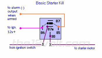
I'm following the basic kill switch wiring that is described in this site but the truck starts even with the alarm activated.  Should I be using a different wiring diagram for the starter kill?

mendozalester 
Member - Posts: 12
Member spacespace
Joined: February 17, 2006
Location: United States
Posted: October 29, 2007 at 1:32 PM / IP Logged  

I used this wiring diagram but the truck starts with alarm activated. ???

97 ford f 150 adding remote start -- posted image.

cderobles 
Member - Posts: 5
Member spacespace
Joined: October 26, 2007
Location: Texas, United States
Posted: October 29, 2007 at 1:43 PM / IP Logged  

make sure the orange wire is ground when arm, which goes to pin 87 on relay,if so you have a bad relay

carlos
Twelvoltz 
Platinum - Posts: 2,384
Platinum spaceThis member has made a donation to the12volt.com. Click here for more info.spaceThis member consistently provides reliable informationspace
Joined: March 24, 2005
Location: New Jersey, United States
Posted: October 29, 2007 at 2:56 PM / IP Logged  
There are many options when hooking up a starter kill circuit. Make sure you followed that diagram precisely. The wire at pin 85 should be at ground when the alarm is armed, or in some cases when the alarm is triggered. The wire at pin 86 needs to provide +12V, they show hooking it to the ignition in that diagram, I prefer to hook it to the key side (so pins 86 and 87a are the same) of the starter circuit so the relay is only energized when the starter circuit is trying to be energized. It is rare to have a bad relay.
Installer, IT support, and FFL. I need less hobbies.

Sorry, you can NOT post a reply.
This topic is closed.

  Printable version Printable version Post ReplyPost New Topic
You cannot post new topics in this forum
You cannot reply to topics in this forum
You cannot delete your posts in this forum
You cannot edit your posts in this forum
You cannot create polls in this forum
You cannot vote in polls in this forum

  •  
Search the12volt.com
Follow the12volt.com Follow the12volt.com on Facebook
Thursday, May 2, 2024 • Copyright © 1999-2024 the12volt.com, All Rights Reserved Privacy Policy & Use of Cookies
Disclaimer: *All information on this site ( the12volt.com ) is provided "as is" without any warranty of any kind, either expressed or implied, including but not limited to fitness for a particular use. Any user assumes the entire risk as to the accuracy and use of this information. Please verify all wire colors and diagrams before applying any information.

Secured by Sectigo
the12volt.com spacer
Support the12volt.com
Top
the12volt.com spacer