the12volt.com spacer
icon

diode wiring with door trigger


Post ReplyPost New Topic
< Prev Topic Next Topic >
ZComplx 
Member - Posts: 5
Member spacespace
Joined: June 23, 2003
Location: United States
Posted: July 01, 2003 at 9:58 PM / IP Logged  

Hi, I'm installing a car starter to my 2003 manual civic coupe.  There are 3 independent door triggers that need to be seperated with diodes.  This is where I don't know where to go...the inputs of the starter is a negative 500mA.  How do I hook up the diodes to seperate the car's door triggers so that it won't short circuit and function properly.   Pretty sure that the negative end of the diodes(gray band is it?) gets hooked up to the trigger input wire and then the positive end of the diode to the car's trigger wire?

Please help.

djfearny2 
Silver - Posts: 810
Silver spaceThis member has made a donation to the12volt.com. Click here for more info.spacespace
Joined: September 23, 2002
Location: United States
Posted: July 01, 2003 at 10:32 PM / IP Logged  
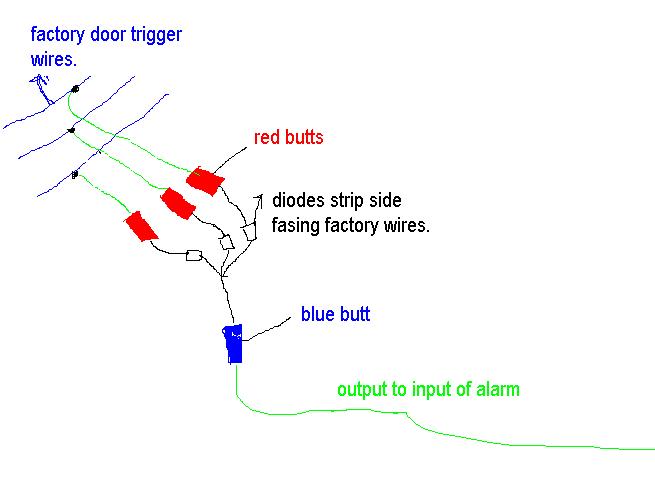
no just take a piece of wire and cut in in three smaller pieces. than strip both ends of those three wires with one having enough strands on it to rap around the triggers wires so take each wire and tap on to each door trigger one wire per door trigger leaving three hanging wires. strip those three ends and take small red butt connectors and put them on each wire. then take three diodes and do the same thign for each wire. take the strip side of diode one and put it in the butt connector and crimp the butt. do the same for the other two wires. now you have three wires hanging with diodes butt connected to each. cut the metal comming from the diode just long enough to be completely covered by the end of the butt connector.
like i said you know how three wires haning each one representing a door trigger. take the other side of the diodes and twist them together again cut off some metal strand just long enough to fit a butt connector on it securely. and then take a blue butt connector and crimp it on the end of those three twisted together diode ends. now only the blue butt connector is left open for a wire. test this before you connect input wire to alarm use a meter that can tell you ground, and basically test all doors when all doors are closed it should rest at nothing. then test each door trigger determining if the blue butt connector meters ground when door is open. close door and proceed to do other doors. after all triggers work connect the door trigger wire from alarm to the open blue butt connector and tape up the whole thing and use a pull tie to secure these wires to a factory harness so that the diodes will not brake.
diode wiring with door trigger -- posted image.
Jon
Installer/Help Technician
---coral springs florida---
mecp certification is not always needed. I have it and it has not helped me out at all. my experience out shines it.

Sorry, you can NOT post a reply.
This topic is closed.

  Printable version Printable version Post ReplyPost New Topic
You cannot post new topics in this forum
You cannot reply to topics in this forum
You cannot delete your posts in this forum
You cannot edit your posts in this forum
You cannot create polls in this forum
You cannot vote in polls in this forum

  •  
Search the12volt.com
Follow the12volt.com Follow the12volt.com on Facebook
Wednesday, May 22, 2024 • Copyright © 1999-2024 the12volt.com, All Rights Reserved Privacy Policy & Use of Cookies
Disclaimer: *All information on this site ( the12volt.com ) is provided "as is" without any warranty of any kind, either expressed or implied, including but not limited to fitness for a particular use. Any user assumes the entire risk as to the accuracy and use of this information. Please verify all wire colors and diagrams before applying any information.

Secured by Sectigo
the12volt.com spacer
Support the12volt.com
Top
the12volt.com spacer