the12volt.com spacer
icon

wiring a small motor relay


Post ReplyPost New Topic
< Prev Topic Next Topic >
batman722 
Member - Posts: 4
Member spacespace
Joined: May 28, 2005
Location: United States
Posted: June 17, 2008 at 12:30 AM / IP Logged  

I've read few a lot of posts and I have a few questions

I want to wire in a small motor to open/close with one toggle switch. The motor opens with the + & - and closes with a reverse of the polarity. I know I can wire it to a 3-way switch but I want it to switch up (open) and switch down (close). The thing that is kinda killing me is that I shouldn't have a constant + to the motor at any time, just a 5 sec to make it open/close. I was looking into a 528t but that's a pulse timed relay and from what I've read I can't keep a constant to it.

I was hoping to have "up" give the + to 5 sec timer to open the motor, then down (reversing the polarity) to a second 5 sec timer to close.

possible or an I just dumb ?

thanks

i am an idiot 
Platinum - Posts: 13,667
Platinum spaceThis member consistently provides reliable informationspace
Joined: September 21, 2006
Location: Louisiana, United States
Posted: June 17, 2008 at 8:49 PM / IP Logged  

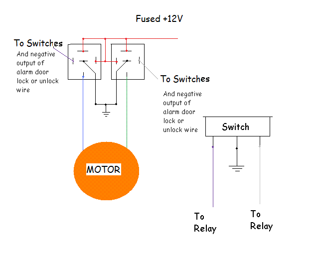
The following relay setup was made for a doorlock setup.  If you have any questions about it, let me know.

wiring a small motor relay -- posted image.

batman722 
Member - Posts: 4
Member spacespace
Joined: May 28, 2005
Location: United States
Posted: June 18, 2008 at 9:55 PM / IP Logged  

wiring a small motor relay -- posted image.

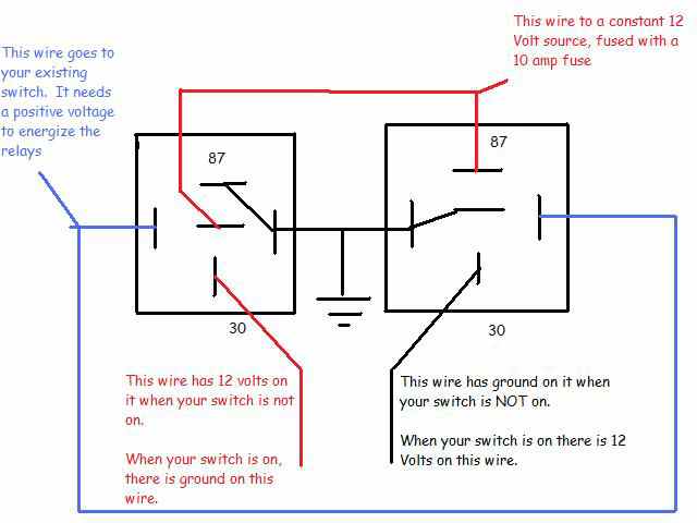
I was thinking something more like this.

But I need at least one of the outputs to be only for 5-10 seconds, not a constant. Any sort of timer relay I could use ?

batman722 
Member - Posts: 4
Member spacespace
Joined: May 28, 2005
Location: United States
Posted: June 18, 2008 at 10:01 PM / IP Logged  
is there a constant to momentary set up I can wire up ?
i am an idiot 
Platinum - Posts: 13,667
Platinum spaceThis member consistently provides reliable informationspace
Joined: September 21, 2006
Location: Louisiana, United States
Posted: June 18, 2008 at 10:08 PM / IP Logged  
That one will not work unless your motor has limit switches that stop it at the end of the stroke.  The drawing I posted is a reversal rest at ground.  when not in use both wires are at ground.  The picture you posted is a reversal but one wire rests at ground and the other rests at 12 volts.  I drew that picture (the one you posted) for a power antenna that had limit switches built into it.  At rest your motor will be turning.  Energize the relays and the motor will turn the other way.  there is no off position on the one you posted.      I do not know of a timer relay that will work for you.  I am sure that there is one out there, I am just not familiar with one.
batman722 
Member - Posts: 4
Member spacespace
Joined: May 28, 2005
Location: United States
Posted: June 18, 2008 at 10:59 PM / IP Logged  

thanks for your input and drawing :)

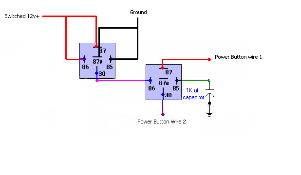
I've been reading on the forum for 2-3 days strait trying to figure this one out. I agree with you about the constant running of the motor and that's bad, so here's another pic I found on the forum, with some questions

wiring a small motor relay -- posted image.

from what I've read this would send a pulse (about .5sec) to wire 1 when + is appied then a seperat pulse to wire 2 when the + is turned off. My one question with this is : is there another/different capacitor I could use to give a longer pulse ? like 3-5 seconds ? what size ?

thanks for the replys.

i am an idiot 
Platinum - Posts: 13,667
Platinum spaceThis member consistently provides reliable informationspace
Joined: September 21, 2006
Location: Louisiana, United States
Posted: June 18, 2008 at 11:14 PM / IP Logged  
From what I am seeing on the above diagram is there will be a pulse generated when the switched voltage is turned on and then another pulse when switched power is removed. The pulse simply connects power wire 1 to power wire 2. There is no separate pulses on wire 1 and wire 2. It simply briefly connects wire 1 to wire 2 when switched power is applied and it does the same when switched power is removed.
The diagram has a 1000 microfarad capacitor. Theoretically a 4700 microfarad capacitor should yield 4.7 times the duration. I did say theoretically, I have not tried this.

Sorry, you can NOT post a reply.
This topic is closed.

  Printable version Printable version Post ReplyPost New Topic
You cannot post new topics in this forum
You cannot reply to topics in this forum
You cannot delete your posts in this forum
You cannot edit your posts in this forum
You cannot create polls in this forum
You cannot vote in polls in this forum

  •  
Search the12volt.com
Follow the12volt.com Follow the12volt.com on Facebook
Monday, April 29, 2024 • Copyright © 1999-2024 the12volt.com, All Rights Reserved Privacy Policy & Use of Cookies
Disclaimer: *All information on this site ( the12volt.com ) is provided "as is" without any warranty of any kind, either expressed or implied, including but not limited to fitness for a particular use. Any user assumes the entire risk as to the accuracy and use of this information. Please verify all wire colors and diagrams before applying any information.

Secured by Sectigo
the12volt.com spacer
Support the12volt.com
Top
the12volt.com spacer