the12volt.com spacer
icon

alarm light


Post ReplyPost New Topic
< Prev Topic Next Topic >
migitcheetah 
Member - Posts: 7
Member spacespace
Joined: November 04, 2008
Location: Oregon, United States
Posted: February 09, 2009 at 2:47 PM / IP Logged  
HI i moved mi alarm LED the little flashing blue light that it came with from the dash to mi grill in the front, and added a few more lights to it so that when i arm the alarm mi grill flashes blue every second instead of the little blue light that used to flash on my dash. but with all the new lights, some are weaker than others and one side flashes brighter and its ot as strong as i would like. i want it really to show blue flashes and right now you kinda have to look hard to see it. what i wanted to know was if i throw in one of theses relay diagrams the Connecting Additional Devices to the Remote Turn On Wire in their will it be able to power more lights properly or will it still do the same thing. and will i still get the flashing or will it be a solid blue. because i like the flashing.
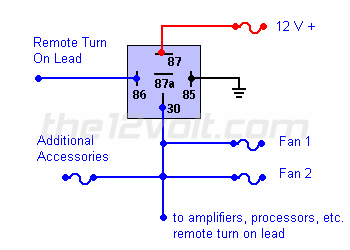
Here is the relay diagram------------------------------------------
Using a 30 amp SPDT relay, connect terminal #87 to constant 12 volts positive with a fuse rated to the sum of the additional accessories you've added and the components you need to turn on. (If you have two fans rated at 5 amps each and a neon light rated at 10 amps, you would use a 20 amp fuse plus 200 ma for each amplifier and processor.) Connect terminal #85 to ground, terminal #86 to the remote turn on wire from the head unit, and terminal #30 to each accessory with an appropriate fuse. A fuse (not shown) could also be used between the output of the relay (#30) and the remote turn on wire of the amplifiers and/or processors for extra precaution.
alarm light -- posted image.
-------------
also would i just hook it up to the + side of the wires or would i have to do one on both sides. or would i use a diferent relay system.
thanks for everything.
KPierson 
Platinum - Posts: 3,527
Platinum spaceThis member consistently provides reliable informationspace
Joined: April 14, 2005
Location: Ohio, United States
Posted: February 09, 2009 at 5:44 PM / IP Logged  

No, that won't work.

If you hook it up and it does light the LEDs, it will kill your battery quickly as the relay will draw too much current for a standby application.

To increase the current coming out of the alarm you need to use a transistor.

Keep in mind though, that if you add all these extra lights the standby time of the battery decreases.

Kevin Pierson
migitcheetah 
Member - Posts: 7
Member spacespace
Joined: November 04, 2008
Location: Oregon, United States
Posted: February 10, 2009 at 12:02 AM / IP Logged  

ok thanks for the advice, but i have another question with the transistor, is their a size or type i need, and would i add one to both positive and negative, or only to the positive. the baterylife im not to woried about because i have 3 yellow tops and if this works im hopeing to put only to strings of LED,s instead of a bunch of little wallmart lights.

KPierson 
Platinum - Posts: 3,527
Platinum spaceThis member consistently provides reliable informationspace
Joined: April 14, 2005
Location: Ohio, United States
Posted: February 10, 2009 at 7:22 AM / IP Logged  

The first thing you need to do is determine how your LED output works.  If it switches the (-) and has a constant positive you would want to use a PNP transistor on the switched (-) output (the most common setup).

If the LED uses a constant ground and a switched (+)5 or (+)12vdc output then you would use an NPN transistor.

The size of the transistor will depend on the load you use.  A smaller transistor, like a 200mA 2n3904 NPN or a 200mA 2n3906 PNP transistor should work, but again it will depend on the current required by the lights you add.

You will also need to know the approximate load and the voltages you want to use to calculate resistor values.  You should have a base resistor and a collector resistor to protect the transistor.  Generic values, assuming you are running a 12vdc output would be ~800 ohm base resistor and a 1/2 watt 47ohm collector resistor.

Kevin Pierson
migitcheetah 
Member - Posts: 7
Member spacespace
Joined: November 04, 2008
Location: Oregon, United States
Posted: February 10, 2009 at 11:39 AM / IP Logged  
now im kinda new to all this, but how exactly would i determine how the output works. would i just hook them up to the battery and use a voltage meter. wouldnt that just show up 12v or so. would it say on the pacage, like the wall plugs have. the little (-)--(o--(+) like that.
alarm light -- posted image.
and how do i determin the load. because a meter would give me 12v since thats whats going from the batery to the lights. would the load also be set on the box ot lights somewhere or is their a mathematical way to find this out.
ill probly go pick up one of each type from radioshack just to be safe. thanks again for all your help.
KPierson 
Platinum - Posts: 3,527
Platinum spaceThis member consistently provides reliable informationspace
Joined: April 14, 2005
Location: Ohio, United States
Posted: February 10, 2009 at 11:55 AM / IP Logged  

Most likely the information won't be published in any way - you'll need a volt meter to figure it out on your own.  The easiest way is to ground your volt meter and find the + pin of the LED.  If it stays constant then you can assume the other pin is (-) and pulsing.  If the (+) voltage turns on and off then your (+) voltage is switching.  Obviously you will need the LED to be flashing to make these measurements.

The load would be determined by adding up the current of each light.  If you are using LEDs you can calculate the current based on the size of the resistor you are using.

Kevin Pierson
migitcheetah 
Member - Posts: 7
Member spacespace
Joined: November 04, 2008
Location: Oregon, United States
Posted: February 10, 2009 at 12:02 PM / IP Logged  
oh ok. that makes sence. thanks so much. that really helped alot. ima go to radioshacktoday and get everything andhopefully try it out tonight.
i ws wonderingalso since youve beensuchabig help with this question, do you know if its possible to have a push buttonstart (like the one on your website) and notneed a key inplace. i know youcan do it with a toggle switch, but i ws wondering if its posible to use the alarms unlock and lock as the togle swich, so that when i unlock the car it thinksthat the key is inplace and kets me push start and drive off, or when i remote start then unlock i can ust sit init and drive off. and then to turn it off if i could make the lock sortof like a kill switch so when i lock the car it willturn off the motor.
KPierson 
Platinum - Posts: 3,527
Platinum spaceThis member consistently provides reliable informationspace
Joined: April 14, 2005
Location: Ohio, United States
Posted: February 10, 2009 at 9:52 PM / IP Logged  
Anything is possible!
Kevin Pierson
migitcheetah 
Member - Posts: 7
Member spacespace
Joined: November 04, 2008
Location: Oregon, United States
Posted: February 10, 2009 at 9:57 PM / IP Logged  
ok so i guess ill have to figure that one out on my own. hru. haha. well thanks alot for all your help. i went out and bought the parts today all i need left are the LED,s and then ill set it up. thanks for everything.

Sorry, you can NOT post a reply.
This topic is closed.

  Printable version Printable version Post ReplyPost New Topic
You cannot post new topics in this forum
You cannot reply to topics in this forum
You cannot delete your posts in this forum
You cannot edit your posts in this forum
You cannot create polls in this forum
You cannot vote in polls in this forum

  •  
Search the12volt.com
Follow the12volt.com Follow the12volt.com on Facebook
Sunday, April 28, 2024 • Copyright © 1999-2024 the12volt.com, All Rights Reserved Privacy Policy & Use of Cookies
Disclaimer: *All information on this site ( the12volt.com ) is provided "as is" without any warranty of any kind, either expressed or implied, including but not limited to fitness for a particular use. Any user assumes the entire risk as to the accuracy and use of this information. Please verify all wire colors and diagrams before applying any information.

Secured by Sectigo
the12volt.com spacer
Support the12volt.com
Top
the12volt.com spacer