the12volt.com spacer
icon

fog light circuit vw 53b


Post ReplyPost New Topic
< Prev Topic Next Topic >
funkydiver 
Member - Posts: 6
Member spacespace
Joined: May 02, 2010
Posted: May 02, 2010 at 5:24 PM / IP Logged  

I am ridding myself of dash mounted switches on my '89 VW Scirocco.  I have decided to retro fit Valeo lighting stalks and just use the connectors in the main body to allow me to do this.  Consequently, I was stumped with the Fog lights as the stalks employ a momentary action to activate the fogs in a Peugeot.

The 12V Acc is a feed from the side lights.

The "Lamps" indicate the existing wiring, so this is all added in instead of the two switches currently on the car.

fog light circuit vw 53b -- posted image.

I have designed this so that to turn rear fogs on, one twist (push of the switch) then to turn front fog lamps on, another twist (another push on the switch)

To turn them off, one twist of hte switch in the opposite direction (push of the off switch) OR remove power from the circuit (turn off the side lights)

I may well change the source of the 12V Acc, as this would mean that the fog lights can remain illuminated with the ignition turned off... a nice battery drainer whilst in the shop and I've forgotten :D

Thoughts and critique is welcome

funkydiver 
Member - Posts: 6
Member spacespace
Joined: May 02, 2010
Posted: May 02, 2010 at 5:58 PM / IP Logged  

hmmm... so now I've posted it up a limitation immediately springs to mind.

Pushing to make the circuit will switch both sets of lights on unless I'm REALLY fast.  Need to integrate some form of timer mechanism, maybe a Capacitor with a recharge rate of say 0.5 seconds inserted (somehow) into the second half of the circuit say on the red trace leading into the two 30 pins on the right hand side?

oldspark 
Gold - Posts: 4,913
Gold spacespace
Joined: November 03, 2008
Location: Australia
Posted: May 03, 2010 at 5:15 AM / IP Logged  
The latching-relay bit can be done simply with something like...
fog light circuit vw 53b -- posted image.
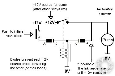
Not that that is a good diagram or description - I just took it from my reply at How to hook up extra battery
... where the "Pump" is the load (lights) and the Feedback arm has a normally closed switch which is pushed open to turn off the load.
Other diagrams are available, but only one person responded to my invite so they have not been made public.    
Food for thought?
funkydiver 
Member - Posts: 6
Member spacespace
Joined: May 02, 2010
Posted: May 03, 2010 at 12:16 PM / IP Logged  

Indeed, I think I get it... however, how is the relay "pushed" open?  That's kinda puzzling me :)

Also, as I have only one switch for two "operations" do I wire this circuit up in a similar manner to the one I posted above?  I'll have a play later and do some jiggery pokery on SmartDraw.

funkydiver 
Member - Posts: 6
Member spacespace
Joined: May 02, 2010
Posted: May 03, 2010 at 3:57 PM / IP Logged  

Had a bit of a mooch on the net for various circuits.

Came across one that utilises a decade timer (which I have, so that helps)

Here's what I came up with

fog light circuit vw 53b -- posted image.

oldspark 
Gold - Posts: 4,913
Gold spacespace
Joined: November 03, 2008
Location: Australia
Posted: May 03, 2010 at 8:49 PM / IP Logged  
I still haven't analysed what you are after etc.
But the 4017 is a 1 of 10 counter that can be used to make a "divide by N" counter (N is from 2 to 10 inclusive). I last used it in a sequential ignition system.
I'm not sure that it is needed in this case.
An inverter package can be used for a simple toggle output from 1 switch.
But for a 3 or more state circuit - eg, all off; 1 on 2 off, 1 & 2 on - then the 4017 is simple to implement - eg output 0 = all off; output 1 via diode to #1; output 2 to #2 & via diode to #1; reset from output 3.
As to my "latching" relay diagram, to release the relay, either cut power to the circuit though normally one would insert a normally closed switch in the output-feedback arm which is pushed open to break the solenoid power.
Hence 2 momentary buttons - the NO for on, the NC for off.
In many installations, a low voltage cutout is added to the feedback line to guard against batter discharge (when powering PCs, fridges, sound systems etc).
As I said, it's not a good diagram. I have a request to the original author for its and another modification.....
funkydiver 
Member - Posts: 6
Member spacespace
Joined: May 02, 2010
Posted: May 04, 2010 at 1:28 AM / IP Logged  

Hi Oldspark,

From what you've said this might well be a workable solution.  I am having to design the circuit around the switches, to operate fog light relays on a car using a rotary momentary switch.

Now in itself the concept is fairly simple.
fog light circuit vw 53b -- posted image.
The fog light switch is on the top left stalk. This is a two section switch, the normal headlights are on the outside end of the stalk, then another rotary momentary section further in for the foglights.
To switch the lights on, you rotate upwards once for rear light, then upwards again for front. To switch off, is rotate down in the same increments, although an all off output with one twist down is fine, if I need the rear fog lights on I can just turn them on again.
Turning the main lights off also resets the fog lights to the off mode.

howie ll 
Pot Metal - Posts: 16,466
Pot Metal spacespace
Joined: January 09, 2007
Location: United Kingdom
Posted: May 07, 2010 at 2:51 PM / IP Logged  
Do you know what's worrying me? The fact that your new switches come from a Peugeot! On late Pugs, they are all switching data not voltage so beware of current loadings.
funkydiver 
Member - Posts: 6
Member spacespace
Joined: May 02, 2010
Posted: May 09, 2010 at 3:09 AM / IP Logged  
True enough Howie, the plan is to give it a go using full on 12 volt, the stalks I have are off a 406 and 307CC, but  I have an extra spare set of stalks anyways so if need be I'll just solder up the new ones, lol.  Worse comes to worse I'll have to drop the current and voltage and operate everything via relays (no biggie, lol)

Sorry, you can NOT post a reply.
This topic is closed.

  Printable version Printable version Post ReplyPost New Topic
You cannot post new topics in this forum
You cannot reply to topics in this forum
You cannot delete your posts in this forum
You cannot edit your posts in this forum
You cannot create polls in this forum
You cannot vote in polls in this forum

  •  
Search the12volt.com
Follow the12volt.com Follow the12volt.com on Facebook
Saturday, May 4, 2024 • Copyright © 1999-2024 the12volt.com, All Rights Reserved Privacy Policy & Use of Cookies
Disclaimer: *All information on this site ( the12volt.com ) is provided "as is" without any warranty of any kind, either expressed or implied, including but not limited to fitness for a particular use. Any user assumes the entire risk as to the accuracy and use of this information. Please verify all wire colors and diagrams before applying any information.

Secured by Sectigo
the12volt.com spacer
Support the12volt.com
Top
the12volt.com spacer