the12volt.com spacer
icon

constant to momentary not pulsing


Post ReplyPost New Topic
< Prev Topic Next Topic >
joebloe4 
Member - Posts: 6
Member spacespace
Joined: January 22, 2011
Posted: January 22, 2011 at 2:16 PM / IP Logged  
Hello all,
Hoping for some help, I can't figure out what I am doing wrong. I used this diagram:
https://www.the12volt.com/relays/page5.asp#ctm
only instead of a 12v momentary pulse, I simply wanted to close a circuit which is usually activated by a momentary button. So I cut the button off of the paired wire and instead of fused 12v going to 87, i have one wire, and instead of a 12v pulse at 30, i have the other wire.
The relay activates, but the circuit stays closed and never re-opens.
I am using this relay:
http://www.radioshack.com/product/index.jsp?productid=2062482
I have ensured the diode is installed in the correct direction, using a 1k uf electrolytic cap, also ensured with the positive end going to the relay, neg end going to ground, and a 10k, 1/2 resistor installed as well.
This system works perfect on power on every time and the capacitor discharges when power is cut, but I am not getting the pulse.
I would appreciate any insight!
joebloe4 
Member - Posts: 6
Member spacespace
Joined: January 22, 2011
Posted: January 22, 2011 at 3:23 PM / IP Logged  
i am wondering if perhaps this mini relay is too small so that even with the current draw from the capacitor, the coil is still staying energized? the dropout voltage is .6 V
oldspark 
Gold - Posts: 4,913
Gold spacespace
Joined: November 03, 2008
Location: Australia
Posted: January 22, 2011 at 5:55 PM / IP Logged  
Bingo! You have it.
In brief, increase the 10k resistor size - try 2x10k in series etc, or 22k etc.
Ignoring the cap, the relay's coil is in series the 10k resistor.
If your relay coil is 1k, that means a voltage across the relay coil of 1/(1+10) = 1/11 time whatever input voltage. eg 12 x 1/11 ~= 1V compared to "hold in" voltage of 0.6V. Ergo, the relay stays on.   
(See wiki-Voltage_divider
If an auto-relay coil is 60R (Ohms) - lets say 100R to be conservative (read: stick with 1's & 10's etc - avoid other digits!!), then the "divider" is 100/(10,000+100) ~= 1/100.
Hence the voltage across the relay coil is 12V x 1/100 = 0.12V - way less than even your hold-in or drop-out voltage.
If you know the resistance of your coil, you can calc the resistor required. But assume say 15-16V input if for car use (since a 12V car system can often be up to 16V for short period).
Or trial & error - add more resistance. (Theory & calcs are great, but "reality" needs to be trialled/tested anyhow....)
FYI:
The larger coil resistance means slower capacitor charge time -(ie longer momentary on time) and the larger resistor means a slower capacitor discharge time - ie, to "reset" in between the "ON" power/voltage/pulses.
Hence the cap size can be reduced.
The resistor should increase in proportion to the increased coil resistance (eg, maybe 500R compared to 60R auto; hence 500/60 x 10k = 83k => 82k or 100k (near enough?)...
And likewise the cap decrease by the same (eg, 1,000uF x 60/500 = 120uF => 100uF etc)...
BUT the different drop-out voltage effects/determines the resistor size.
IE - the RC "momentary on" time constant is coil-resistance times the capacitance; and the the coil-resistance & Resistor must "voltage divide" lower than the relay drop out voltage.
The Resistor then determines the Capacitor's "discharge" time when in input power is removed, but this may not be important. (IE - if next time you turn the power on, the relay does not pulse.)
BTW - if you are happy with this relay - forget what that other jerk wrote (elsewhere) about using auto relays for their spade connectors - though his inference about circuit changes is correct - but that's not such a big deal is it? (You actually learn some good principles with this relay.)
joebloe4 
Member - Posts: 6
Member spacespace
Joined: January 22, 2011
Posted: January 23, 2011 at 10:59 AM / IP Logged  
Thanks oldspark for your very informative post!!
According to the package, resistance across the coil is 400 ohm +/- 10%, while my meter confirms it is right around 370 (bravo, radio shack!).
So, it seem we'd be looking at 400/(400 + 10,000) * 12 = .46, which should be working in theory, or using 16 V which is .62, just slightly above the threshold, which perhaps accounts for my issues.
Working with 20k would seem to certainly sort this issue out, though as you say perhaps some tweaking is involved out there in the real world.
However, this morning with the current 10k setup, I took some readings and found the voltage across the coil to be 2.5-3.5 V, and the voltage across the capacitor to be around 8.5-9.5V.
This seems to go against our calculations by a pretty large magnitude.
Did I measure things the wrong way or is something else at play here?
Despite the cold and snow and lack of a test bench, I am having quite a bit of fun putting my old school studies to practical use. Definitely won't be listening to that other guy's nonsense about automotive relays... though I appreciate his response and he seemed pretty knowledgeable constant to momentary not pulsing -- posted image.
joebloe4 
Member - Posts: 6
Member spacespace
Joined: January 22, 2011
Posted: January 23, 2011 at 7:44 PM / IP Logged  
well I'm finally a happy man! I'm not sure where the issue was, but I started from scratch with the new suggested values, 100 uf and 100k ohm, and found while it pulses reliably, the discharging was a bit too slow, somewhere around 25 seconds. I then switched out the resistor on a whim to the also suggested 2 10k's in series, which works a treat and brought the discharge time down to about 3 seconds.
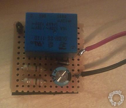
I attempted to make it look presentable with a little bit of perfboard, just for kicks. I won't be showing the back side of it constant to momentary not pulsing -- posted image.
constant to momentary not pulsing -- posted image.
Again, lots of thanks, oldspark!! I don't see this little experiment having gone as cheaply or quickly without your knowledge.
oldspark 
Gold - Posts: 4,913
Gold spacespace
Joined: November 03, 2008
Location: Australia
Posted: January 24, 2011 at 2:37 PM / IP Logged  
Shucks... thanks!
I'm glad you did do it this way rather than the wimp's way (or bad adviser's way LOL!) - who needs a spade-type auto relay??!
Let's face it - yours is smaller, quieter, and more educational. ("Everything is the same, only different." - in this case, coil resistance and drop-pot voltage, hence.....)
I see you are already an expert at matrix board assembly - at least of my standard. (Track-side = censored.)
I reckon it's the board that makes things untidy, hence I omit it. "Free-air bird's nests" might be the common name. (Of the Dove or Pigeon type!) Also quit censorable, else epoxy pottable!   
TIP - Never try to tidy up a working bird's nest or transfer to specially designed PCB - the circuit will fail! (IE - If it works, leave it alone!)
joebloe4 
Member - Posts: 6
Member spacespace
Joined: January 22, 2011
Posted: January 25, 2011 at 2:23 PM / IP Logged  
Soooo... about that earlier problem: Doing the math for 400/(400 + x) * 12 = 3.5 yields x to be 977. Taking a second look at the parts I pulled off after starting from scratched revealed a rouge 1K resistor.
Who'd have thunk a little red stripe could make such a difference??
Seriously, this has been great... I have another one in the works now to automatically hit the reboot button on my car PC on power up. I have purchased a SSD HD which doesn't like cold booting and only gets picked up during POST after hitting ALT-CTRL-DEL. I won't be beholden to any motherboard manufacturer and their belated BIOS updates!!
This little relay should fit nicely and cleanly inside the housing, which is why I played around with the board. 'pigeon nest', haha! My trunk is looking more like a rat's nest! And I'm with you 100%, I try to touch it all as infrequently as possible. I have a spare box of fuses on the occasions where I must...
oldspark 
Gold - Posts: 4,913
Gold spacespace
Joined: November 03, 2008
Location: Australia
Posted: January 25, 2011 at 4:16 PM / IP Logged  
Le rouge as in brown black red = 1+0+00 = 1,000 = 1k?
Alas the pain of the "tens" - 1k is "red" (two zeros), not "orange" (3 zeros") - unless it is brown as with brown black black brown for 1% etc resistors.
These days I use my multimeter! (At least to confirm the "zeros".)
BTW - now that I know the application (eg, PC, not "automotive"), all the more points to you - education AND elegance! (What - a big clunky relay in a laptop etc?)
PS - seen the relays in "chips" - typically 1k coils and can switch about 1A to 2A? They often look like 14-pin DIL (Dual In Line) integrated circuits with missing pins. EG - I use one to control a dash voltmeter.
joebloe4 
Member - Posts: 6
Member spacespace
Joined: January 22, 2011
Posted: February 01, 2011 at 8:31 AM / IP Logged  
This first circuit I made was actually to activate my AV switcher, which toggles between the carPC and the stock navigation system with the use of a momentary button. Unfortunately, on power off it does not remember the input it was previously set on and always defaulted to the navigation. Ideally, I'd find a way for it to save the input setting (any thoughts??), but as a runner up solution, I've got this working to default to carPC at least.
Working with the PC relay (and with you) gave me the know how to put together the second circuit, which I quick spliced into the carPC's ATX power supply and ran to the reset pins on the mobo, and it works flawlessly..!
I was concerned that I'd need to figure out a way to incorporate some kind of delay, but the reset occurs before the POST screen even comes up and it still does the trick -- the SSD is detected every time! Really thrilled to see this drive in action instead of collecting dust on my desk, as it has done for the last 3 months... at a cost of 5 bucks in lieu of a new motherboard (which likely would not have had video outputs compatible with my AV switcher and so on and so on). Just like the Master Card commercials -- really priceless.
chaminda 
Member - Posts: 8
Member spacespace
Joined: February 01, 2011
Location: New Zealand
Posted: February 05, 2011 at 3:26 AM / IP Logged  
H
To sound stupid does 1k uf mean 1000uf. Thought that was quite a large amount?
Page of 2

  Printable version Printable version Post ReplyPost New Topic
You cannot post new topics in this forum
You cannot reply to topics in this forum
You cannot delete your posts in this forum
You cannot edit your posts in this forum
You cannot create polls in this forum
You cannot vote in polls in this forum

  •  
Search the12volt.com
Follow the12volt.com Follow the12volt.com on Facebook
Tuesday, May 14, 2024 • Copyright © 1999-2024 the12volt.com, All Rights Reserved Privacy Policy & Use of Cookies
Disclaimer: *All information on this site ( the12volt.com ) is provided "as is" without any warranty of any kind, either expressed or implied, including but not limited to fitness for a particular use. Any user assumes the entire risk as to the accuracy and use of this information. Please verify all wire colors and diagrams before applying any information.

Secured by Sectigo
the12volt.com spacer
Support the12volt.com
Top
the12volt.com spacer