the12volt.com spacer
icon

Relay setup


Post ReplyPost New Topic
< Prev Topic Next Topic >
bumpinranger97 
Member - Posts: 2
Member spacespace
Joined: November 27, 2004
Location: United States
Posted: October 30, 2005 at 11:43 PM / IP Logged  

Ok I have a six pin DIN connected to a device with the following properties:

Relay Dry Contact Closure (Pins 2 & 3)

When the accessory relay is energized, its contacts

close and present a short across pins 2 and 3 of the
connector. The relay contacts are rated for 10 watts,
maximum at 28 volts dc/ac rms. Within the limits of
the 10 watt rating, the closed contacts will handle up
to 750 milliamperes continuously and will switch up to
400 milliamperes of current.

Relay Closure Timing Control (Pins 4 & 5)

Pins 4 and 5 of the accessory connector are used to

select the time duration of the relay contact closure.
If these two pins are NOT used (open circuit), the relay
will remain energized for approximately 10 seconds after
an alert is received. If pins 4 & 5 are SHORTED, the relay
will remain energized until the 'RESET' button on the front
of the device is depressed. Pressing the 'RESET' button
causes the contacts to open and turns off the ALERT indicator."

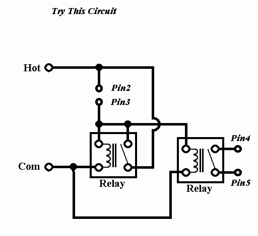
I need to have a 24volt steady output when the device is energized and turn off with the rest button, what circuit do I need to make for this to happen?

Thanks for any help!

bumpinranger97 
Member - Posts: 2
Member spacespace
Joined: November 27, 2004
Location: United States
Posted: October 31, 2005 at 3:30 PM / IP Logged  
Anybody????
hotwaterwizard 
Silver - Posts: 1,350
Silver spacespace
Joined: December 11, 2003
Location: California, United States
Posted: November 09, 2005 at 11:42 PM / IP Logged  

The Question is loaded to mean more than one thing.

Do you want it to have 24v after the reset is pushed?

Before and After?

What about the Time Delay on or off?

Be more specific.

John DeRosa (Hotwaterwizard)
Stockton California
When in doubt, try it out !
hotwaterwizard 
Silver - Posts: 1,350
Silver spacespace
Joined: December 11, 2003
Location: California, United States
Posted: November 10, 2005 at 12:03 AM / IP Logged  

Relay setup -- posted image.

USE 24v RELAYS For this circuit.

John DeRosa (Hotwaterwizard)
Stockton California
When in doubt, try it out !
hotwaterwizard 
Silver - Posts: 1,350
Silver spacespace
Joined: December 11, 2003
Location: California, United States
Posted: November 10, 2005 at 12:07 AM / IP Logged  

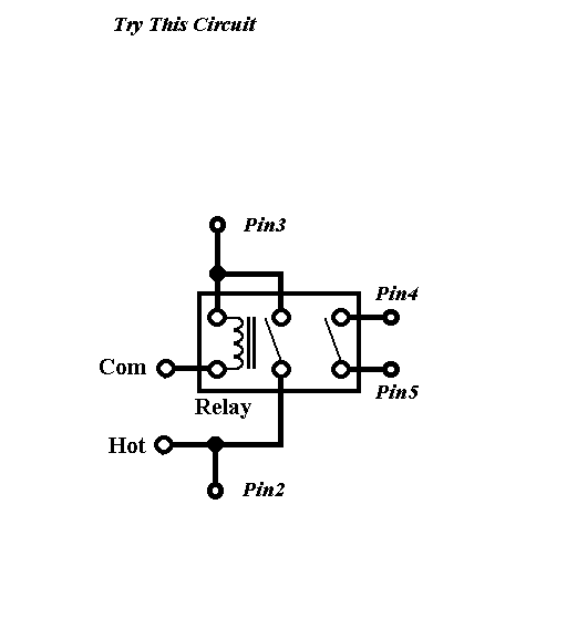
IF you use a DPST Relay you can use only 1 relay. LOAD OUTPUT Will connect to pin 3

Relay setup -- posted image.

John DeRosa (Hotwaterwizard)
Stockton California
When in doubt, try it out !

Sorry, you can NOT post a reply.
This topic is closed.

  Printable version Printable version Post ReplyPost New Topic
You cannot post new topics in this forum
You cannot reply to topics in this forum
You cannot delete your posts in this forum
You cannot edit your posts in this forum
You cannot create polls in this forum
You cannot vote in polls in this forum

  •  
Search the12volt.com
Follow the12volt.com Follow the12volt.com on Facebook
Friday, May 17, 2024 • Copyright © 1999-2024 the12volt.com, All Rights Reserved Privacy Policy & Use of Cookies
Disclaimer: *All information on this site ( the12volt.com ) is provided "as is" without any warranty of any kind, either expressed or implied, including but not limited to fitness for a particular use. Any user assumes the entire risk as to the accuracy and use of this information. Please verify all wire colors and diagrams before applying any information.

Secured by Sectigo
the12volt.com spacer
Support the12volt.com
Top
the12volt.com spacer