the12volt.com spacer
icon

Schematic for two Leds


Post ReplyPost New Topic
< Prev Topic Next Topic >
sxng9 
Member - Posts: 4
Member spacespace
Joined: March 19, 2006
Location: United States
Posted: March 19, 2006 at 1:25 AM / IP Logged  

I need to power two Leds (one blue and the other orange), but not at the same time.  I was looking at the schematic for the "Radio On Until Door Opened" and I am completely stumped how I could modify it to power two Leds, instead of the 'radio'.  My requirements are this:

1) A 12v power source will keep the blue Led lit indefinately until another 12v power source triggers it (while the blue Led is lit, the orange Led is not lit).

2) When the 'other' 12v power source triggers it, the orange Led will be lit and the blue Led will be unlit.

3) When the 'other' 12v power source that triggers the orange Led is disconnected or untriggered, the blue Led will come back on - orange Led becomes unlit.

Can someone post a quick schematic using relay(s) that can do this?  Thanks - it will be used inside a car.

sxng9 
Member - Posts: 4
Member spacespace
Joined: March 19, 2006
Location: United States
Posted: March 19, 2006 at 1:36 AM / IP Logged  

Generally, what I am saying above is two power sources, two Leds and each power source operates each Led - but only one Led can be lit at a time.  Thanks again.

sxng9 
Member - Posts: 4
Member spacespace
Joined: March 19, 2006
Location: United States
Posted: March 19, 2006 at 12:30 PM / IP Logged  

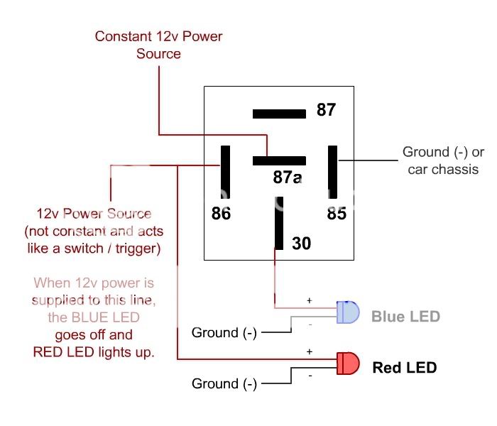
Nevermind, I figured it out using one relay.  Below is a simple schematic that I made and tested out.  Does anyone else see any problems that I could run into?  This will be installed in a car.  Basically, the 12v constant power will be fed from one of the dimmer power lights that will be used to power the BLUE LEDs and the other 12v power will be from the VTEC power line (jn a Honda Civic), so when VTEC kicks in, the RED / AMBER LED will light on and the BLUE LED will light off.

Schematic for two Leds -- posted image.

bmwpwner 
Copper - Posts: 174
Copper spacespace
Joined: January 28, 2006
Location: United States
Posted: March 22, 2006 at 9:38 PM / IP Logged  
yep that diagram should do it. btw, you will probably need to put a 300mA resistor inline with EACH LED. most LED's can't take a straight +12volt input for very long without burning out. good luck.
"I cannot teach anybody anything, I can only make them think."
-Socrates-
KPierson 
Platinum - Posts: 3,527
Platinum spaceThis member consistently provides reliable informationspace
Joined: April 14, 2005
Location: Ohio, United States
Posted: March 22, 2006 at 10:34 PM / IP Logged  

I personally would do it a little different, but that should work.

I would connect your VTEC wire to pin 86 like you have shown, but I would NOT hook the LED up there.

Connect Pin 30 to 12vdc.

Connect the 87A terminal to the 'off' LED
Connect the 87 terminal to the 'on' LED

Ground each LED, and pin 85, and like bmwpwner said put a current limiting reistor inline with the 12vdc fed at pin 30 to protect the LEDs.

I always thought you could tell VTEC turned on because it made all the trees around you blurry.  Or is that when you push the N20 button???  Sorry, could't post without a Vtec joke.

Kevin Pierson

Sorry, you can NOT post a reply.
This topic is closed.

  Printable version Printable version Post ReplyPost New Topic
You cannot post new topics in this forum
You cannot reply to topics in this forum
You cannot delete your posts in this forum
You cannot edit your posts in this forum
You cannot create polls in this forum
You cannot vote in polls in this forum

  •  
Search the12volt.com
Follow the12volt.com Follow the12volt.com on Facebook
Friday, May 3, 2024 • Copyright © 1999-2024 the12volt.com, All Rights Reserved Privacy Policy & Use of Cookies
Disclaimer: *All information on this site ( the12volt.com ) is provided "as is" without any warranty of any kind, either expressed or implied, including but not limited to fitness for a particular use. Any user assumes the entire risk as to the accuracy and use of this information. Please verify all wire colors and diagrams before applying any information.

Secured by Sectigo
the12volt.com spacer
Support the12volt.com
Top
the12volt.com spacer