the12volt.com spacer
icon

turn signal/marker light alternation


Post ReplyPost New Topic
< Prev Topic Next Topic >
myspivey 
Member - Posts: 4
Member spacespace
Joined: June 18, 2007
Posted: June 19, 2007 at 10:02 AM / IP Logged  
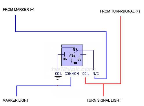
So i did a quick search and could not find what i was looking for. Here is what im looking to happen: I have a marker light and a turn signal on the car. These are both an extra set over the normal ones but ties into the same 12v feed. Its on a Nissan 03 350z. I want the marker light to turn off when the turn signal is active. So when the turn signal is lit, the marker light will not be. When the turn signal goes off, the marker comes back on. I tried doing this myself but it doesn't seem to be working so i cant figure out what i have done wrong. As of right now here is what i have. turn signal/marker light alternation -- posted image. My friend things i should reverse 87a and 30 and tap 87 into a ground. Would this solve my problem? Or do i need a second relay. Any help would be appreciated. Thanks!
dualsport 
Silver - Posts: 983
Silver spacespace
Joined: September 27, 2005
Location: United States
Posted: June 20, 2007 at 7:44 AM / IP Logged  
If your side marker light bulbs are relatively low power compared to the turn signal bulbs, which they normally would be, you can try this-
Connect the marker light(-) to the turn signal(+) feed, and the marker light(+) to the marker light(+) feed.
When the turn signals come on, the marker light gets 12V on both sides of the bulb, which turns it off.
When the turn signal comes on while the marker light is off, the marker lights will flash along with the turn signals, at half brightness, which helps to alert drivers along the side that you're turning.
If the side markers are drawing more power than usual, this may not work as well, because it relies on the turn signals acting as a ground when they're off. If the markers draw the same power as the turn signal bulbs, then all the bulbs will glow at half brightness when the side markers are turned on. This shouldn't be a problem unless the extra markers you added are some serious wattage.
myspivey 
Member - Posts: 4
Member spacespace
Joined: June 18, 2007
Posted: June 20, 2007 at 10:04 AM / IP Logged  
Ya, i saw that post in the forum, cant do it. The + and - are hard wired. The ground is shared by both marker and turn signal so i cant isolate one ground from the other. What i don't get is why the power would matter since the relay is placed before the lights so it would seem to be the power the lights are using wouldn't matter since the car is feeding it the same 12v no matter what.
dualsport 
Silver - Posts: 983
Silver spacespace
Joined: September 27, 2005
Location: United States
Posted: June 21, 2007 at 1:20 AM / IP Logged  
Not sure what you mean by hardwired, but the idea is to cut the wire to the side marker that's currently going to ground and rewire it to the turn signal feed. The original ground to the marker light won't be used, so there's no need to isolate it. If by hardwired you mean it doesn't use wires but instead has some kind of printed circuit connection that you can't rewire, then it may be simpler to just use the relay.
In your diagram, all you need to do is to change the relay term 86 connection to a ground, rather than the TURN SIGNAL LIGHT you have shown there. Then when you have the marker lights on, and turn the turn signals on, it'll break the connection and turn the marker lights off.
You'll need to cut wires either way you do it, so adding the relays doesn't help in that respect.
myspivey 
Member - Posts: 4
Member spacespace
Joined: June 18, 2007
Posted: June 21, 2007 at 10:02 AM / IP Logged  
Yes its a circuit type board so marker and turn signal share the same ground wire so i cant change them. As for the relay. With your example, how does the turn signal then get power? If 86 is a ground, what am i doing with that cable thats the power feed for the turn signal? All im doing that that point is directly grounding the power feed for the turn signal rather than passing it on to the turn signal light. Correct?
dualsport 
Silver - Posts: 983
Silver spacespace
Joined: September 27, 2005
Location: United States
Posted: June 21, 2007 at 11:45 PM / IP Logged  
In your diagram above, just change the words that say "TURN SIGNAL LIGHT" to "GROUND".
Your turn signal light is going to be directly connected to the "FROM TURN SIGNAL (+), and isn't going to go to the contacts of the relay.
You only need to tap off the signal to control the relay. In your diagram, I assume you didn't cut the wire from the turn signal (+) going to the Turn Signal lamp, because that wouldn't have worked at all, since you have the relay coil between them. It has to be left directly connected.
Only the marker light power goes through the relay, just as you've drawn.
I'd draw it out, but if you just change the words in your drawing, it'd be the same.
myspivey 
Member - Posts: 4
Member spacespace
Joined: June 18, 2007
Posted: June 22, 2007 at 9:27 AM / IP Logged  
So something like this.
turn signal/marker light alternation -- posted image.
dualsport 
Silver - Posts: 983
Silver spacespace
Joined: September 27, 2005
Location: United States
Posted: June 22, 2007 at 4:55 PM / IP Logged  
That's it- give it a try.

Sorry, you can NOT post a reply.
This topic is closed.

  Printable version Printable version Post ReplyPost New Topic
You cannot post new topics in this forum
You cannot reply to topics in this forum
You cannot delete your posts in this forum
You cannot edit your posts in this forum
You cannot create polls in this forum
You cannot vote in polls in this forum

  •  
Search the12volt.com
Follow the12volt.com Follow the12volt.com on Facebook
Saturday, April 27, 2024 • Copyright © 1999-2024 the12volt.com, All Rights Reserved Privacy Policy & Use of Cookies
Disclaimer: *All information on this site ( the12volt.com ) is provided "as is" without any warranty of any kind, either expressed or implied, including but not limited to fitness for a particular use. Any user assumes the entire risk as to the accuracy and use of this information. Please verify all wire colors and diagrams before applying any information.

Secured by Sectigo
the12volt.com spacer
Support the12volt.com
Top
the12volt.com spacer