


remote start/alarm 02 trans am m6
Home /
the12volt's Install Bay /
Vehicle Wiring Information & File Requests / remote start/alarm 02 trans am m6 ( Topic Closed)
Welcome Guest :)


Posted: December 27, 2014 at 10:47 AM / IP Logged
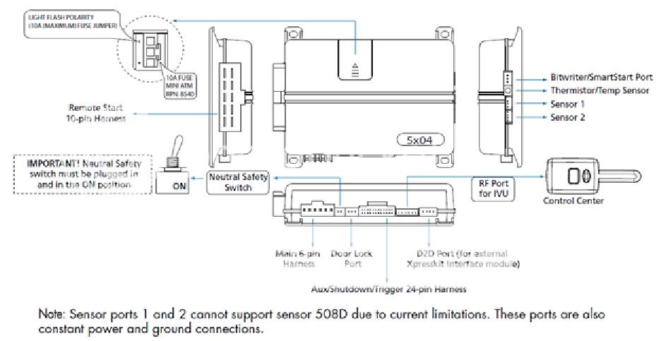
I'm getting ready to install a Viper 5204V Remote Start/Alarm with an XK06 module and 535T window module into my manual 02 Trans Am WS6. I've been researching this for months and have read everything I could find. I still have a few unanswered questions. The following is what I've compiled so far. The questions are marked, "???".
Note: I intend to do all the connections at the BCM, where possible.
I'd like to go ahead and say Thank You for your time and help.
 Main Harness (H1), 6-pin connector


 Main Harness (H1), 6-pin connector
-
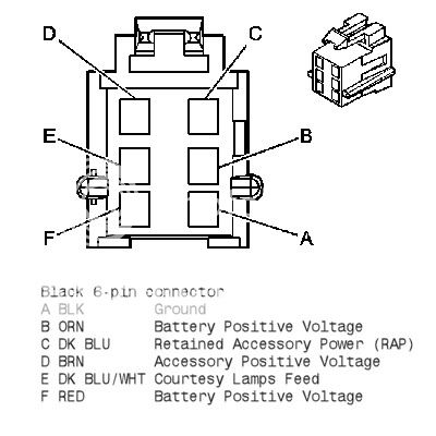
[*]H1/1 RED (+)12VDC CONSTANT INPUT
-
[*]Backside of the fuse box open slot
[*]Look for orange wire (BATT)
-
[*]25AMP Fuse
-
[*]put a ring terminal on and attach to a factory bolt attached to a good amount of metal
[*]Passenger side next to door
-
[*]siren red wire already as stated will attach to the brown off the viper
[*]black Siren wire will be grounded to another good metal point.
-
[*]N/A
-
[*]Working behind the fuse box
[*]Brown wire coming off the Headlight switch assembly
-
[*]Use blue quick slice connector to switch into this brown
-
[*]Connection will be made to a positive 12V wire, so ensure your alarms output for this feature is also +12V
-
[*]H2/1 PINK/WHITE (-) 200mA IGNITION/FLEX RELAY CONTROL OUTPUT
[*]H2/2 BLACK/ WHITE (-) NEUTRAL SAFETY INPUT
[*]H2/3 BLUE/WHITE (-) 200mA 2ND STATUS /REAR DEFOGGER OUTPUT
-
[*]Need a relay to operate the defrost/defogger
-
[*]85 = 5902 Blue/White
[*]86 = Fused 12V
[*]87 = Defogger Gray
[*]30 = Fused 12V
-
[*]Port 85 Trunk Pop Relay
-
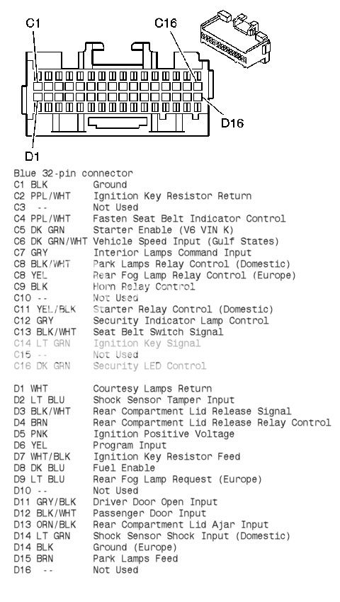
[*]BCM D1 White Courtesy Lamp Return
[*]Blue Splice
-
[*]Connect to H2/6
-
[*]N/A
-
[*]H3/1 PINK (+) IGNITION 1 INPUT/OUTPUT
-
[*]Key Cylinder Option
-
[*]connect to the Pink wire coming off the key cylinder
-
[*](thicker gauge shows 12v only when key is at the run position right before crank)
-
[*]starter kill relay you take the starter wire on the car Yellow wire and cut the wire in half one end goes to the green wire the other to the black wire. (Green and Black Wire Thicker)
-
[*](thicker gauge coming off key cylinder)
[*](there may what looks like a yellow wire but it may not be it may be a yellow shield with multiple wires inside DO NOT TOUCH THIS IS AND AIRBAG WIRE. also yellow plugs are airbag wires too!!!)
-
[*]It is best to get ignition power from the fuse panel. There are ports there specifically designed by GM for adding accessories. They are labeled BATT, ACCY, and IGN. The IGN port is the one you want for this purpose.
-
[*]Look for Yellow wire
[*]??? Or should this be for H3/1 ???
-
[*](thicker wire that always will show 12v)
-
[*]Need 2 relays, for our purposes relay x and y
-
[*]85x to 85y to constant +12V source
-
[*]???Can use same source for trunk pop/red off fuse block???
-
[*]Anode side of a diode
-
[*]connect to the grey with a black stripe wire coming off the BCM D11
-
[*]test this the voltage will change with the dome-light turning on and off.
-
[*]ORANGE / Black Unlock wire off the BCM D on 6-pin connector
-
[*]will show 12v then when you press and hold unlock it will drop to 0v
-
[*]86x
-
[*]86y
-
[*]Need Standard Automotive Relay
[*]RED / White Stripe
[*]Go to port 85 on relay
-
[*]H2/5 RED / White (-) 200mA TRUNK RELEASE OUTPUT
-
[*]Attach to a constant 12v source
-
[*](can attach to our red off fuse block)
-
[*]BCM
-
[*]Brown wire in the blue plug on the BCM D4.
[*]test this wire it will sit at 0v when probed the jump to 12v when you press the trunk release button in the car.
-
[*]BLACK/ White wire
[*]Splice a wire to it thatll be ran to the relay
[*]test this wire it will sit at 0v when probed the jump to 12v when you press the trunk release button in the car.

Posted: December 27, 2014 at 11:07 AM / IP Logged
So I didn't realize I couldn't edit my post. The original post had some outdated information. Let's try this again.
Main Harness (H1), 6-pin connector
H1/1 RED (+)12VDC CONSTANT INPUT
.....Backside of the fuse box open slot
........Look for orange wire (BATT)
........25AMP Fuse
H1/2 BLACK (-) CHASSIS GROUND
.....put a ring terminal on and attach to a factory bolt attached to a good amount of metal
.....Passenger side next to door
H1/3 BROWN (+) SIREN OUTPUT
.....siren red wire already as stated will attach to the brown off the viper
.....black Siren wire will be grounded to another good metal point.
H1/4 WHITE/ BROWN PARKING LIGHT ISOLATION WIRE - PIN 87a of onboard relay
.....N/A
H1/5 WHITE PARKING LIGHT OUTPUT
.....Working behind the fuse box
.....Brown wire coming off the Headlight switch assembly
........Use blue quick slice connector to switch into this brown
.....???Am I good here???
........Connection will be made to a positive 12V wire, so ensure your alarms output for this feature is also +12V
........This is where I set the alarms LIGHT FLASH POLARITY to positive correct?
H1/6 ORANGE (-) 500mA GROUND WHEN ARMED OUTPUT
.....XK06 connect after programming
.....Connect to Window Module H2/4 ORANGE
Start Kill Relay place between the remote start connection (H3/4&5) and starter
.....Diode
........86 (anode) to 85
.....86 & 30
........Starter wire, ignition switch side
.....87a
........Starter wire, starter solenoid side
.....85
........Starter Interrupt Wire from Alarm
........H1/6 ORANGE (-) 500mA GROUND WHEN ARMED OUTPUT
H2 Harness, 24-pin connector
H2/1 PINK/WHITE (-) 200mA IGNITION/FLEX RELAY CONTROL OUTPUT
H2/2 BLACK/ WHITE (-) NEUTRAL SAFETY INPUT
.....E Brake Switch
H2/3 BLUE/WHITE (-) 200mA 2ND STATUS /REAR DEFOGGER OUTPUT
.....Need a relay to operate the defrost/defogger
........85 = 5204 Blue/White
........86 = Fused 12V
........87 = Defogger Gray
........30 = Fused 12V
.....Rear Defrost ....... Gray (+) ......... At Rear Window Defogger Switch
H2/4 GREEN/ BLACK (-) 200mA OEM ALARM DISARM OUTPUT
.....N/A
H2/5 RED / WHITE (-) 200mA TRUNK RELEASE OUTPUT
.....Port 85 Trunk Pop Relay
H2/6 GREEN (-) DOOR TRIGGER INPUT (N/C* OR N/O)
.....2 Options both at BCM, both use Blue Splices, use (-) BCM option. Positive BCM Option goes to H2/12
........BCM D1 White Courtesy Lamp Return
........BCM D11 GRY/BLK Driver Door Open Input and D12 BLK/WHT Passenger DOI
H2/7 BLACK / YELLOW (-) 200mA DOME LIGHT SUPERVISION OUTPUT
.....Connect to H2/6
H2/8 BROWN / BLACK (-) 200mA HORN HONK OUTPUT
.....Horn Wire ???Where???
H2/9 DARK BLUE (-) 200mA STATUS OUTPUT
H2/10 PINK (-) 200mA IGNITION 1 OUTPUT
H2/11 WHITE/ BLACK (-) 200mA AUX 3 OUTPUT
H2/12 VIOLET (+) DOOR TRIGGER INPUT
.....???BCM D1 Courtesy Lamps Return???
H2/13 WHITE/ VIOLET (-) 200mA AUX 1 OUTPUT
.....Window Module 535T-H2/3 RED / WHITE Wire
H2/14 VIOLET/BLACK (-) 200mA AUX 2 OUTPUT
H2/15 ORANGE / BLACK (-) 200mA AUX 4 OUTPUT
H2/16 BROWN (+) BRAKE SHUTDOWN INPUT
.....Switch on the Brake Pedal
H2/17 GREY (-) HOOD PIN INPUT (N/C OR N/O)
.....Hood Pin Switch connection, if used.
H2/18 VIOLET / YELLOW (-) 200mA STARTER OUTPUT
.....N/A
H2/19 BLUE (-) TRUNK PIN/ INSTANT TRIGGER INPUT (N/C OR N/O)
.....Trunk Input
........BCM D13 ORN/BLK Rear Compartment Lid Ajar Input
H2/20 GREY/BLACK (-) DIESEL WAIT TO START INPUT
.....N/A
H2/21 WHITE/ BLUE (-) REMOTE START/ TURBO TIMER ACTIVATION INPUT
.....N/A
H2/22 ORANGE (-) 200mA ACCESSORY OUTPUT
H2/23 VIOLET/WHITE TACHOMETER INPUT
.....PCM connect ???where???
H2/24 GREEN / WHITE (-) 200mA OEM ALARM ARM OUTPUT
.....N/A
Remote Start, (H3) 10-pin connector
H3/1 PINK (+) IGNITION 1 INPUT/OUTPUT
.....BCM Option
........Connect to D5 Pink Wire
..........(shows 12v only when key is at the run position right before crank)
.....Key Cylinder Option
........connect to the Pink wire coming off the key cylinder
..........(thicker gauge shows 12v only when key is at the run position right before crank)
H3/2 RED / WHITE (87) FLEX RELAY +12V INPUT (30A FUSED)
.....N/A
H3/3 ORANGE (+) ACCESSORY OUTPUT
H3/4 VIOLET (+) STARTER OUTPUT (CAR SIDE OF THE STARTER KILL)
.....See H3/5
H3/5 GREEN (+) STARTER INPUT (KEY SIDE OF THE STARTER KILL)
.....starter kill relay you take the starter wire on the car Purple wire near BCM or Yellow wire on steering column and cut the wire in half one end goes to the green wire the other to the violet wire. (Green and Violet Wire Thicker)
........(thicker gauge coming off key cylinder)
........(there may what looks like a yellow wire but it may not be it may be a yellow shield with multiple wires inside DO NOT TOUCH THIS IS AND AIRBAG WIRE. also yellow plugs are airbag wires too!!!)
H3/6 RED IGNITION 1 +12V INPUT (30A FUSED)
.....It is best to get ignition power from the fuse panel. There are ports there specifically designed by GM for adding accessories. They are labeled BATT, ACCY, and IGN. The IGN port is the one you want for this purpose.
........Look for Yellow wire
.....connects to the red wire coming off the key cylinder
........(thicker wire that always will show 12v)
H3/7 PINK/WHITE (30) FLEX RELAY OUTPUT (car side of ign, acc or starter wire)
H3/8 PINK/BLACK (87a) FLEX RELAY INPUT (key side of ign, acc or starter wire if needed)
H3/9 RED / BLACK ACCESSORY/STARTER RELAY +12V INPUT (30A FUSED)
.....???BCM C11 YEL/BLK Starter Relay Control (Domestic)???
H3/10 NC No Connection
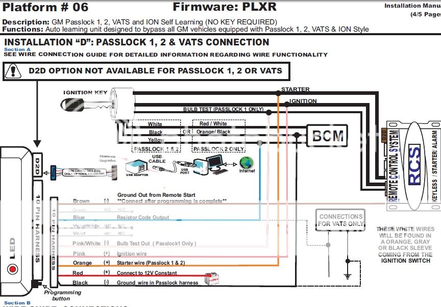 XK06 Firmware PLXR
PIN#1 Brown (-) Ground Out from Remote Start
.....H1/6 ORANGE (-) 500mA GROUND WHEN ARMED OUTPUT
........Connect after programming XK06
PIN#2 Green
.....N/A
PIN#3 Blue Resistor Code Output
.....VATS White Resistance Wire
.....???Possibly BCM D7 WHT/BLK Ignition Key Resistor Feed???
PIN#4 Violet/White
.....N/A
PIN#5 Violet
.....N/A
PIN#6 Pink/White
.....N/A
PIN#7 Pink (+) Ignition Wire
.....BCM D5 with H3/1
PIN#8 Orange (+) Starter Wire
.....VATS
........N/A
PIN#9 Red (+) +12V Constant
.....Connect to H1/1
PIN#10 Black (-)
.....VATS White wire coming out
........Will show true ground without key in cylinder
.....???Possibly BCM C2 PPL/WHT Ignition Key Resistor Return???
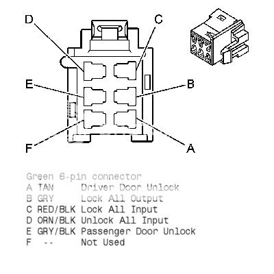
Door Lock, 3-pin connector
Reference from/for diagrams: http://www.bfranker.badz28.com/fbody/alarm96up3.htm
Need 2 relays, for our purposes relay x and y
.....85x to 85y to constant +12V source
........???Can use same source for trunk pop/red off fuse block???
.....87x to 87y to Ground Source
.....86x to BLUE (-) 500mA UNLOCK OUTPUT
.....86y to GREEN (-) 500mA LOCK OUTPUT
.....30x to unlock wire diodes
.....30y to lock wire
Need 2 1amp or 2 amp diodes
.....Anode side of a diode
........connect to the grey with a black stripe wire coming off the BCM D11
..........test this the voltage will change with the dome-light turning on and off.
.....Anode side of a diode
........ORANGE / Black Unlock wire off the BCM D on 6-pin connector
..........will show 12v then when you press and hold unlock it will drop to 0v
BLUE (-) 500mA UNLOCK OUTPUT
.....86x
EMPTY NOT USED
GREEN (-) 500mA LOCK OUTPUT
.....86y
Trunk Pop
Need Standard Automotive Relay
RED / White Stripe
Go to port 85 on relay
.....H2/5 RED / White (-) 200mA TRUNK RELEASE OUTPUT
port 86 and 87 on relay
.....Attach to a constant 12v source
........(can attach to our red off fuse block)
port 30 on Relay 2 OPTIONS
.....BCM
........Brown wire in the blue plug on the BCM D4.
........test this wire it will sit at 0v when probed the jump to 12v when you press the trunk release button in the car.
Hatch release Relay
.....BLACK/ White wire
.....Splice a wire to it thatll be ran to the relay
.....test this wire it will sit at 0v when probed the jump to 12v when you press the trunk release button in the car.
XK06 Firmware PLXR
PIN#1 Brown (-) Ground Out from Remote Start
.....H1/6 ORANGE (-) 500mA GROUND WHEN ARMED OUTPUT
........Connect after programming XK06
PIN#2 Green
.....N/A
PIN#3 Blue Resistor Code Output
.....VATS White Resistance Wire
.....???Possibly BCM D7 WHT/BLK Ignition Key Resistor Feed???
PIN#4 Violet/White
.....N/A
PIN#5 Violet
.....N/A
PIN#6 Pink/White
.....N/A
PIN#7 Pink (+) Ignition Wire
.....BCM D5 with H3/1
PIN#8 Orange (+) Starter Wire
.....VATS
........N/A
PIN#9 Red (+) +12V Constant
.....Connect to H1/1
PIN#10 Black (-)
.....VATS White wire coming out
........Will show true ground without key in cylinder
.....???Possibly BCM C2 PPL/WHT Ignition Key Resistor Return???
Door Lock, 3-pin connector
Reference from/for diagrams: http://www.bfranker.badz28.com/fbody/alarm96up3.htm
Need 2 relays, for our purposes relay x and y
.....85x to 85y to constant +12V source
........???Can use same source for trunk pop/red off fuse block???
.....87x to 87y to Ground Source
.....86x to BLUE (-) 500mA UNLOCK OUTPUT
.....86y to GREEN (-) 500mA LOCK OUTPUT
.....30x to unlock wire diodes
.....30y to lock wire
Need 2 1amp or 2 amp diodes
.....Anode side of a diode
........connect to the grey with a black stripe wire coming off the BCM D11
..........test this the voltage will change with the dome-light turning on and off.
.....Anode side of a diode
........ORANGE / Black Unlock wire off the BCM D on 6-pin connector
..........will show 12v then when you press and hold unlock it will drop to 0v
BLUE (-) 500mA UNLOCK OUTPUT
.....86x
EMPTY NOT USED
GREEN (-) 500mA LOCK OUTPUT
.....86y
Trunk Pop
Need Standard Automotive Relay
RED / White Stripe
Go to port 85 on relay
.....H2/5 RED / White (-) 200mA TRUNK RELEASE OUTPUT
port 86 and 87 on relay
.....Attach to a constant 12v source
........(can attach to our red off fuse block)
port 30 on Relay 2 OPTIONS
.....BCM
........Brown wire in the blue plug on the BCM D4.
........test this wire it will sit at 0v when probed the jump to 12v when you press the trunk release button in the car.
Hatch release Relay
.....BLACK/ White wire
.....Splice a wire to it thatll be ran to the relay
.....test this wire it will sit at 0v when probed the jump to 12v when you press the trunk release button in the car.
 XK06 Firmware PLXR
PIN#1 Brown (-) Ground Out from Remote Start
.....H1/6 ORANGE (-) 500mA GROUND WHEN ARMED OUTPUT
........Connect after programming XK06
PIN#2 Green
.....N/A
PIN#3 Blue Resistor Code Output
.....VATS White Resistance Wire
.....???Possibly BCM D7 WHT/BLK Ignition Key Resistor Feed???
PIN#4 Violet/White
.....N/A
PIN#5 Violet
.....N/A
PIN#6 Pink/White
.....N/A
PIN#7 Pink (+) Ignition Wire
.....BCM D5 with H3/1
PIN#8 Orange (+) Starter Wire
.....VATS
........N/A
PIN#9 Red (+) +12V Constant
.....Connect to H1/1
PIN#10 Black (-)
.....VATS White wire coming out
........Will show true ground without key in cylinder
.....???Possibly BCM C2 PPL/WHT Ignition Key Resistor Return???
Door Lock, 3-pin connector
Reference from/for diagrams: http://www.bfranker.badz28.com/fbody/alarm96up3.htm
Need 2 relays, for our purposes relay x and y
.....85x to 85y to constant +12V source
........???Can use same source for trunk pop/red off fuse block???
.....87x to 87y to Ground Source
.....86x to BLUE (-) 500mA UNLOCK OUTPUT
.....86y to GREEN (-) 500mA LOCK OUTPUT
.....30x to unlock wire diodes
.....30y to lock wire
Need 2 1amp or 2 amp diodes
.....Anode side of a diode
........connect to the grey with a black stripe wire coming off the BCM D11
..........test this the voltage will change with the dome-light turning on and off.
.....Anode side of a diode
........ORANGE / Black Unlock wire off the BCM D on 6-pin connector
..........will show 12v then when you press and hold unlock it will drop to 0v
BLUE (-) 500mA UNLOCK OUTPUT
.....86x
EMPTY NOT USED
GREEN (-) 500mA LOCK OUTPUT
.....86y
Trunk Pop
Need Standard Automotive Relay
RED / White Stripe
Go to port 85 on relay
.....H2/5 RED / White (-) 200mA TRUNK RELEASE OUTPUT
port 86 and 87 on relay
.....Attach to a constant 12v source
........(can attach to our red off fuse block)
port 30 on Relay 2 OPTIONS
.....BCM
........Brown wire in the blue plug on the BCM D4.
........test this wire it will sit at 0v when probed the jump to 12v when you press the trunk release button in the car.
Hatch release Relay
.....BLACK/ White wire
.....Splice a wire to it thatll be ran to the relay
.....test this wire it will sit at 0v when probed the jump to 12v when you press the trunk release button in the car.
XK06 Firmware PLXR
PIN#1 Brown (-) Ground Out from Remote Start
.....H1/6 ORANGE (-) 500mA GROUND WHEN ARMED OUTPUT
........Connect after programming XK06
PIN#2 Green
.....N/A
PIN#3 Blue Resistor Code Output
.....VATS White Resistance Wire
.....???Possibly BCM D7 WHT/BLK Ignition Key Resistor Feed???
PIN#4 Violet/White
.....N/A
PIN#5 Violet
.....N/A
PIN#6 Pink/White
.....N/A
PIN#7 Pink (+) Ignition Wire
.....BCM D5 with H3/1
PIN#8 Orange (+) Starter Wire
.....VATS
........N/A
PIN#9 Red (+) +12V Constant
.....Connect to H1/1
PIN#10 Black (-)
.....VATS White wire coming out
........Will show true ground without key in cylinder
.....???Possibly BCM C2 PPL/WHT Ignition Key Resistor Return???
Door Lock, 3-pin connector
Reference from/for diagrams: http://www.bfranker.badz28.com/fbody/alarm96up3.htm
Need 2 relays, for our purposes relay x and y
.....85x to 85y to constant +12V source
........???Can use same source for trunk pop/red off fuse block???
.....87x to 87y to Ground Source
.....86x to BLUE (-) 500mA UNLOCK OUTPUT
.....86y to GREEN (-) 500mA LOCK OUTPUT
.....30x to unlock wire diodes
.....30y to lock wire
Need 2 1amp or 2 amp diodes
.....Anode side of a diode
........connect to the grey with a black stripe wire coming off the BCM D11
..........test this the voltage will change with the dome-light turning on and off.
.....Anode side of a diode
........ORANGE / Black Unlock wire off the BCM D on 6-pin connector
..........will show 12v then when you press and hold unlock it will drop to 0v
BLUE (-) 500mA UNLOCK OUTPUT
.....86x
EMPTY NOT USED
GREEN (-) 500mA LOCK OUTPUT
.....86y
Trunk Pop
Need Standard Automotive Relay
RED / White Stripe
Go to port 85 on relay
.....H2/5 RED / White (-) 200mA TRUNK RELEASE OUTPUT
port 86 and 87 on relay
.....Attach to a constant 12v source
........(can attach to our red off fuse block)
port 30 on Relay 2 OPTIONS
.....BCM
........Brown wire in the blue plug on the BCM D4.
........test this wire it will sit at 0v when probed the jump to 12v when you press the trunk release button in the car.
Hatch release Relay
.....BLACK/ White wire
.....Splice a wire to it thatll be ran to the relay
.....test this wire it will sit at 0v when probed the jump to 12v when you press the trunk release button in the car.Posted: December 27, 2014 at 11:19 AM / IP Logged
 Dipswitch 1 2 window/4 window mode
.....On/Off
Dipswitch 2 One Touch Control
.....On/Off
Dipswitch 3 Window Switch Polarity
.....On/Off
Dipswitch 4 Not Used
.....On/Off
Dipswitch 5 Siren Input Polarity
.....On/Off
Dipswitch 6 Prewarn/Full trigger Close
.....On/Off
535T-H1/1 VIOLET Driver-Side Ground Path Input for down(-)
.....wire provides the ground path for the driver-side motor down side.
.....Connect this wire to a paint-free surface on the vehicle chassis. Use a factory bolt if possible.
535T-H1/2 GREEN Driver-Side Down Motor Output (+)
.....Cut the driver-side down wire (BROWN) at the switch or motor and connect this wire to the motor side of the wire.
535T-H1/3 BLUE Driver-Side Up Motor Input (+)
.....Cut the driver up wire (DARK BLUE) at the switch or motor and connect this wire to the motor side of the up wire
535T-H1/4 RED (+)12V Constant, 20A Fused (+)
.....Connect 12V source off the fuse box, powering the system
535T-H1/5 BLACK (-) Chassis Ground
.....Connect this wire to a paint-free surface on the vehicle chassis. Use a factory bolt if possible.
.....IMPORTANT! Do not ground the 535T to the vehicle door. The 535T requires a solid ground to function properly, and the door hinges do not provide sufficient ground to the vehicles chassis.
535T-H1/6 VIOLET/BLACK Passenger-Side Ground Path Input (-)
.....wire provides the ground path for the passenger side motor.
.....Connect this wire to a paint-free surface on the vehicle chassis. Use a factory bolt if possible.
535T-H1/7 GREEN/ BLACK Passenger-Side Down Motor Output (+)
.....Cut the passenger-side down wire (TAN) at the switch and connect this wire to the motor side of the down wire.
535T-H1/8 BLUE/BLACK Passenger-Side Up Motor Output (+)
.....Cut the passenger-side up wire (LIGHT BLUE) at the switch and connect this wire to the motor side of the up wire.
535T-H2/1 BROWN Driver Window up switch
.....Cut the driver up wire at the switch or motor and connect wire to the switch side of the wire
535T-H2/2 WHITE Driver down switch
.....Cut the driver down wire at the switch or motor and connect the wire to the switch side of the wire
535T-H2/3 RED / WHITE AUX Input (-)
.....Connect wire to H2/13
535T-H2/4 ORANGE Ground when Armed Input (-)
.....Connect to H1/6
.....Note: Window switch inputs of the 535T are not active when 535T-H2/4 has a ground with remote start systems. 535T-H2/4 wire also activates when the system is remote started. To prevent the windows from rolling up upon remote start, program off the ???anti-grind feature???.
535T-H2/5 GREY Output during Activation (-) 500 mA
.....Connect wire to an optional relay to bypass sensors which may trigger security system during operation of the 535T
535T-H2/6 BROWN / BLACK Passenger Up Switch
.....Cut passenger up wire at the switch or motor and connect this to the switch side of the wire
535T-H2/7 WHITE/ BLACK Passenger Down Switch
.....Cut passenger down switch or motor and connect this wire to the switch side of the wire
535T-H3/1 WHITE Driver Motor Ground path for Up (-)
.....Connect to a good ground point
535T-H3/2 WHITE/ BLACK Passenger Motor Ground path for up (-)
.....Connect to a good ground point
535T-H3/3 GREY/RED Stop Input (-)
.....535T will cease movement when this wire receives a negative pulse
.....Optional: Connect wire to a switch or Aux Output
.....Note: Can be used in conjunction with a sunroof limit switch
535T-H3/4 GREY/BLACK Delay Input (-)
.....Prevents 535T from moving windows as long as its receiving a ground. Blah, Blah, Blah
.....Optional for staggered systems
535T-H3/5 BROWN Siren Trigger Close Input (-/+)
.....Connect to the siren output of security system
.....Wire will roll up the windows when it receives negative or positive (programmable via dip switch 5) from the security systems siren output when the security system has been armed with the windows down.
Feel free to tell me I'm nuts and I've got something completely screwed up.
Dipswitch 1 2 window/4 window mode
.....On/Off
Dipswitch 2 One Touch Control
.....On/Off
Dipswitch 3 Window Switch Polarity
.....On/Off
Dipswitch 4 Not Used
.....On/Off
Dipswitch 5 Siren Input Polarity
.....On/Off
Dipswitch 6 Prewarn/Full trigger Close
.....On/Off
535T-H1/1 VIOLET Driver-Side Ground Path Input for down(-)
.....wire provides the ground path for the driver-side motor down side.
.....Connect this wire to a paint-free surface on the vehicle chassis. Use a factory bolt if possible.
535T-H1/2 GREEN Driver-Side Down Motor Output (+)
.....Cut the driver-side down wire (BROWN) at the switch or motor and connect this wire to the motor side of the wire.
535T-H1/3 BLUE Driver-Side Up Motor Input (+)
.....Cut the driver up wire (DARK BLUE) at the switch or motor and connect this wire to the motor side of the up wire
535T-H1/4 RED (+)12V Constant, 20A Fused (+)
.....Connect 12V source off the fuse box, powering the system
535T-H1/5 BLACK (-) Chassis Ground
.....Connect this wire to a paint-free surface on the vehicle chassis. Use a factory bolt if possible.
.....IMPORTANT! Do not ground the 535T to the vehicle door. The 535T requires a solid ground to function properly, and the door hinges do not provide sufficient ground to the vehicles chassis.
535T-H1/6 VIOLET/BLACK Passenger-Side Ground Path Input (-)
.....wire provides the ground path for the passenger side motor.
.....Connect this wire to a paint-free surface on the vehicle chassis. Use a factory bolt if possible.
535T-H1/7 GREEN/ BLACK Passenger-Side Down Motor Output (+)
.....Cut the passenger-side down wire (TAN) at the switch and connect this wire to the motor side of the down wire.
535T-H1/8 BLUE/BLACK Passenger-Side Up Motor Output (+)
.....Cut the passenger-side up wire (LIGHT BLUE) at the switch and connect this wire to the motor side of the up wire.
535T-H2/1 BROWN Driver Window up switch
.....Cut the driver up wire at the switch or motor and connect wire to the switch side of the wire
535T-H2/2 WHITE Driver down switch
.....Cut the driver down wire at the switch or motor and connect the wire to the switch side of the wire
535T-H2/3 RED / WHITE AUX Input (-)
.....Connect wire to H2/13
535T-H2/4 ORANGE Ground when Armed Input (-)
.....Connect to H1/6
.....Note: Window switch inputs of the 535T are not active when 535T-H2/4 has a ground with remote start systems. 535T-H2/4 wire also activates when the system is remote started. To prevent the windows from rolling up upon remote start, program off the ???anti-grind feature???.
535T-H2/5 GREY Output during Activation (-) 500 mA
.....Connect wire to an optional relay to bypass sensors which may trigger security system during operation of the 535T
535T-H2/6 BROWN / BLACK Passenger Up Switch
.....Cut passenger up wire at the switch or motor and connect this to the switch side of the wire
535T-H2/7 WHITE/ BLACK Passenger Down Switch
.....Cut passenger down switch or motor and connect this wire to the switch side of the wire
535T-H3/1 WHITE Driver Motor Ground path for Up (-)
.....Connect to a good ground point
535T-H3/2 WHITE/ BLACK Passenger Motor Ground path for up (-)
.....Connect to a good ground point
535T-H3/3 GREY/RED Stop Input (-)
.....535T will cease movement when this wire receives a negative pulse
.....Optional: Connect wire to a switch or Aux Output
.....Note: Can be used in conjunction with a sunroof limit switch
535T-H3/4 GREY/BLACK Delay Input (-)
.....Prevents 535T from moving windows as long as its receiving a ground. Blah, Blah, Blah
.....Optional for staggered systems
535T-H3/5 BROWN Siren Trigger Close Input (-/+)
.....Connect to the siren output of security system
.....Wire will roll up the windows when it receives negative or positive (programmable via dip switch 5) from the security systems siren output when the security system has been armed with the windows down.
Feel free to tell me I'm nuts and I've got something completely screwed up.
 Dipswitch 1 2 window/4 window mode
.....On/Off
Dipswitch 2 One Touch Control
.....On/Off
Dipswitch 3 Window Switch Polarity
.....On/Off
Dipswitch 4 Not Used
.....On/Off
Dipswitch 5 Siren Input Polarity
.....On/Off
Dipswitch 6 Prewarn/Full trigger Close
.....On/Off
535T-H1/1 VIOLET Driver-Side Ground Path Input for down(-)
.....wire provides the ground path for the driver-side motor down side.
.....Connect this wire to a paint-free surface on the vehicle chassis. Use a factory bolt if possible.
535T-H1/2 GREEN Driver-Side Down Motor Output (+)
.....Cut the driver-side down wire (BROWN) at the switch or motor and connect this wire to the motor side of the wire.
535T-H1/3 BLUE Driver-Side Up Motor Input (+)
.....Cut the driver up wire (DARK BLUE) at the switch or motor and connect this wire to the motor side of the up wire
535T-H1/4 RED (+)12V Constant, 20A Fused (+)
.....Connect 12V source off the fuse box, powering the system
535T-H1/5 BLACK (-) Chassis Ground
.....Connect this wire to a paint-free surface on the vehicle chassis. Use a factory bolt if possible.
.....IMPORTANT! Do not ground the 535T to the vehicle door. The 535T requires a solid ground to function properly, and the door hinges do not provide sufficient ground to the vehicles chassis.
535T-H1/6 VIOLET/BLACK Passenger-Side Ground Path Input (-)
.....wire provides the ground path for the passenger side motor.
.....Connect this wire to a paint-free surface on the vehicle chassis. Use a factory bolt if possible.
535T-H1/7 GREEN/ BLACK Passenger-Side Down Motor Output (+)
.....Cut the passenger-side down wire (TAN) at the switch and connect this wire to the motor side of the down wire.
535T-H1/8 BLUE/BLACK Passenger-Side Up Motor Output (+)
.....Cut the passenger-side up wire (LIGHT BLUE) at the switch and connect this wire to the motor side of the up wire.
535T-H2/1 BROWN Driver Window up switch
.....Cut the driver up wire at the switch or motor and connect wire to the switch side of the wire
535T-H2/2 WHITE Driver down switch
.....Cut the driver down wire at the switch or motor and connect the wire to the switch side of the wire
535T-H2/3 RED / WHITE AUX Input (-)
.....Connect wire to H2/13
535T-H2/4 ORANGE Ground when Armed Input (-)
.....Connect to H1/6
.....Note: Window switch inputs of the 535T are not active when 535T-H2/4 has a ground with remote start systems. 535T-H2/4 wire also activates when the system is remote started. To prevent the windows from rolling up upon remote start, program off the ???anti-grind feature???.
535T-H2/5 GREY Output during Activation (-) 500 mA
.....Connect wire to an optional relay to bypass sensors which may trigger security system during operation of the 535T
535T-H2/6 BROWN / BLACK Passenger Up Switch
.....Cut passenger up wire at the switch or motor and connect this to the switch side of the wire
535T-H2/7 WHITE/ BLACK Passenger Down Switch
.....Cut passenger down switch or motor and connect this wire to the switch side of the wire
535T-H3/1 WHITE Driver Motor Ground path for Up (-)
.....Connect to a good ground point
535T-H3/2 WHITE/ BLACK Passenger Motor Ground path for up (-)
.....Connect to a good ground point
535T-H3/3 GREY/RED Stop Input (-)
.....535T will cease movement when this wire receives a negative pulse
.....Optional: Connect wire to a switch or Aux Output
.....Note: Can be used in conjunction with a sunroof limit switch
535T-H3/4 GREY/BLACK Delay Input (-)
.....Prevents 535T from moving windows as long as its receiving a ground. Blah, Blah, Blah
.....Optional for staggered systems
535T-H3/5 BROWN Siren Trigger Close Input (-/+)
.....Connect to the siren output of security system
.....Wire will roll up the windows when it receives negative or positive (programmable via dip switch 5) from the security systems siren output when the security system has been armed with the windows down.
Feel free to tell me I'm nuts and I've got something completely screwed up.
Dipswitch 1 2 window/4 window mode
.....On/Off
Dipswitch 2 One Touch Control
.....On/Off
Dipswitch 3 Window Switch Polarity
.....On/Off
Dipswitch 4 Not Used
.....On/Off
Dipswitch 5 Siren Input Polarity
.....On/Off
Dipswitch 6 Prewarn/Full trigger Close
.....On/Off
535T-H1/1 VIOLET Driver-Side Ground Path Input for down(-)
.....wire provides the ground path for the driver-side motor down side.
.....Connect this wire to a paint-free surface on the vehicle chassis. Use a factory bolt if possible.
535T-H1/2 GREEN Driver-Side Down Motor Output (+)
.....Cut the driver-side down wire (BROWN) at the switch or motor and connect this wire to the motor side of the wire.
535T-H1/3 BLUE Driver-Side Up Motor Input (+)
.....Cut the driver up wire (DARK BLUE) at the switch or motor and connect this wire to the motor side of the up wire
535T-H1/4 RED (+)12V Constant, 20A Fused (+)
.....Connect 12V source off the fuse box, powering the system
535T-H1/5 BLACK (-) Chassis Ground
.....Connect this wire to a paint-free surface on the vehicle chassis. Use a factory bolt if possible.
.....IMPORTANT! Do not ground the 535T to the vehicle door. The 535T requires a solid ground to function properly, and the door hinges do not provide sufficient ground to the vehicles chassis.
535T-H1/6 VIOLET/BLACK Passenger-Side Ground Path Input (-)
.....wire provides the ground path for the passenger side motor.
.....Connect this wire to a paint-free surface on the vehicle chassis. Use a factory bolt if possible.
535T-H1/7 GREEN/ BLACK Passenger-Side Down Motor Output (+)
.....Cut the passenger-side down wire (TAN) at the switch and connect this wire to the motor side of the down wire.
535T-H1/8 BLUE/BLACK Passenger-Side Up Motor Output (+)
.....Cut the passenger-side up wire (LIGHT BLUE) at the switch and connect this wire to the motor side of the up wire.
535T-H2/1 BROWN Driver Window up switch
.....Cut the driver up wire at the switch or motor and connect wire to the switch side of the wire
535T-H2/2 WHITE Driver down switch
.....Cut the driver down wire at the switch or motor and connect the wire to the switch side of the wire
535T-H2/3 RED / WHITE AUX Input (-)
.....Connect wire to H2/13
535T-H2/4 ORANGE Ground when Armed Input (-)
.....Connect to H1/6
.....Note: Window switch inputs of the 535T are not active when 535T-H2/4 has a ground with remote start systems. 535T-H2/4 wire also activates when the system is remote started. To prevent the windows from rolling up upon remote start, program off the ???anti-grind feature???.
535T-H2/5 GREY Output during Activation (-) 500 mA
.....Connect wire to an optional relay to bypass sensors which may trigger security system during operation of the 535T
535T-H2/6 BROWN / BLACK Passenger Up Switch
.....Cut passenger up wire at the switch or motor and connect this to the switch side of the wire
535T-H2/7 WHITE/ BLACK Passenger Down Switch
.....Cut passenger down switch or motor and connect this wire to the switch side of the wire
535T-H3/1 WHITE Driver Motor Ground path for Up (-)
.....Connect to a good ground point
535T-H3/2 WHITE/ BLACK Passenger Motor Ground path for up (-)
.....Connect to a good ground point
535T-H3/3 GREY/RED Stop Input (-)
.....535T will cease movement when this wire receives a negative pulse
.....Optional: Connect wire to a switch or Aux Output
.....Note: Can be used in conjunction with a sunroof limit switch
535T-H3/4 GREY/BLACK Delay Input (-)
.....Prevents 535T from moving windows as long as its receiving a ground. Blah, Blah, Blah
.....Optional for staggered systems
535T-H3/5 BROWN Siren Trigger Close Input (-/+)
.....Connect to the siren output of security system
.....Wire will roll up the windows when it receives negative or positive (programmable via dip switch 5) from the security systems siren output when the security system has been armed with the windows down.
Feel free to tell me I'm nuts and I've got something completely screwed up.Posted: December 27, 2014 at 11:21 AM / IP Logged
Crap this should have read.
Dipswitch 1 2 window/4 window mode
.....Off
Dipswitch 2 One Touch Control
.....Off
Dipswitch 3 Window Switch Polarity
.....On
Dipswitch 4 Not Used
.....Off
Dipswitch 5 Siren Input Polarity
.....Off
Dipswitch 6 Prewarn/Full trigger Close
.....Off
Posted: December 27, 2014 at 2:04 PM / IP Logged
Moderators I apologize for having posted this thread in the wrong forum. I've already relocated it. If you could, please delete it.
Posted: December 30, 2014 at 6:20 PM / IP Logged
Almost done, need just a little help finishing.
Clutch:
I'm installing a remote start onto a manual. So I'm thinking that I need to make the car think the clutch is engaged when I try to remote start the car. There's 2 wires connecting to sensor behind the clutch. Purple and BLACK/ white if I remember correctly.
Which is the output that I'd need to wire into?
Which of my viper wires would I use to tie into the wire identified above? I'm thinking it's the H3/3 ORANGE (+) ACCESSORY OUTPUT on the (Remote Start, (H3) 10-pin connector), but that's a SWAG on my part.
Brake:
I "need" to wire the Viper H2/16 BROWN (+) BRAKE SHUTDOWN INPUT in. I'm assuming this needs to be wired to one of the wires behind the brake. There's a about a half dozen wires, so I don't know where to begin to guess.
Which of the wires is an output and which is the best to connect to?
What would the consequence be if I didn't connect the H2/16 wire?
Tachometer
I need to wire the Viper H2/23 VIOLET/WHITE TACHOMETER INPUT. I'm thinking the wire the feeds the tachometer in the console cluster would be where I'd want to tie this in. However, I don't have a clue which wire this is.
Can someone please identify that wire and the best place to access it?
Thanks!
Sorry, you can NOT post a reply.
This topic is closed.
 Printable version
| You cannot post new topics in this forum You cannot reply to topics in this forum You cannot delete your posts in this forum You cannot edit your posts in this forum You cannot create polls in this forum You cannot vote in polls in this forum |

| Search the12volt.com |
Follow the12volt.com 
Monday, April 29, 2024 • Copyright © 1999-2024 the12volt.com, All Rights Reserved • Privacy Policy & Use of Cookies

Monday, April 29, 2024 • Copyright © 1999-2024 the12volt.com, All Rights Reserved • Privacy Policy & Use of Cookies
Disclaimer:
*All information on this site ( the12volt.com ) is provided "as is" without any warranty of any kind, either expressed or implied, including but not limited to fitness for a particular use. Any user assumes the entire risk as to the accuracy and use of this information. Please
verify all wire colors and diagrams before applying any information.
