the12volt.com spacer
icon

ford 2008 f 350 avital 4103 , pkall


Post ReplyPost New Topic
< Prev Topic Next Topic >
tim051 
Member - Posts: 13
Member spacespace
Joined: July 31, 2013
Location: Texas, United States
Posted: August 05, 2013 at 7:00 PM / IP Logged  

Hmm, looks like the message was moved to this thread.

Figured it would be more visible & of more importance to other folks with a separate thread.

Oh well.

Thanks Trini for the reply (you got it to me before it moved).  That's the problem... there's no Yellow/Orange wire!!

Thanks

Tim
kreg357 
Platinum - Posts: 7,783
Platinum spaceThis member has made a donation to the12volt.com. Click here for more info.spaceThis member has been recognized as an authority in Electrical Theory. Click here for more info.spaceThis member has been recognized as an authority in Mobile Security and Convenience. Click here for more info.spacespace
Joined: January 30, 2009
Location: Pennsylvania, United States
Posted: August 05, 2013 at 9:09 PM / IP Logged  
Here is the Plug you are looking for ( Type E, 4 Pin ). This is from a 2012 Lincoln MKZ and they did swap the Pin 3 & 4 colors.
ford 2008 f 350 avital 4103 , pkall - Page 2 -- posted image.
You should be able to get a plain metal key and give it a try. Watch the dash for the security light. Only crank once and if it fails to start, then use a working key next and start the engine to clear everything.
Soldering is fun!
tim051 
Member - Posts: 13
Member spacespace
Joined: July 31, 2013
Location: Texas, United States
Posted: August 06, 2013 at 2:28 PM / IP Logged  

Hi Kreg,

No joy on the key here in podunks'ville!  Well, it's not really necessary at this point... if it doesn't work, then I'll 'tape' the key close until I figure out the DATA lines issue.

Going through the harnesses to test wires - this is a FYI for those in my boat.  If you try and ground the GRAY line on the Headlamp switch to turn on the Parking lights, it won't work the way you'd think.  Ground it and wait 6 seconds.  Then the parking lights will come on.  Not really adequate for blink-blink signalling!

The issue is that in the 'off' position, there is a line that goes to a micro & parking lamp relay at the SJB (per Fords wiring diagram).  When you turn on the parking lamps, the switch wiper goes off of the 'OFF' position, then grounds the 'PARK' connection. Guess it doesn't like two lines grounded at the same time!

Looking at the 4103s installation manual, it says that the H1/9 connection (LIGHT FLASH OUTPUT), is configured for a + output, meaning that it will provide +12v whenever it is 'on'.  It also says in a note at the bottom of the page that ... for parking light systems that draw 10 amps or more... add a relay...  Does that mean if my parking lamps only draw between 4 and 5 amps that I can use this line directly?  I'd hate to smoke some FET inside the 4103 if it's not rated for up to 10 amps.  

If it's not good for the 5 amps, I'll probably put a small relay behind the Headlamp switch and do it that way as opposed to running wires to the SJB & putting a relay there.  (This old man can more easily access the headlamp switch than the SJB)! :-)

Thanks

Tim
tim051 
Member - Posts: 13
Member spacespace
Joined: July 31, 2013
Location: Texas, United States
Posted: August 06, 2013 at 3:36 PM / IP Logged  

Disregard the last question about how much current the parking lamp line can handle.

There is a 10A fuse in line with the white wire!  Didn't see till I started the installation!

Thanks

Tim
kreg357 
Platinum - Posts: 7,783
Platinum spaceThis member has made a donation to the12volt.com. Click here for more info.spaceThis member has been recognized as an authority in Electrical Theory. Click here for more info.spaceThis member has been recognized as an authority in Mobile Security and Convenience. Click here for more info.spacespace
Joined: January 30, 2009
Location: Pennsylvania, United States
Posted: August 06, 2013 at 5:28 PM / IP Logged  
From Page 1
"I have found that it is easier / safer to make some of the R/S connections at the SJB. The SJB is in the passenger
kick panel. You will have to extend the 4103's wires to reach. You should get the locks and the Parking Light (+)
wires at the SJB. ( Do not use the (-) Parking Light wire at the Headlight switch.)"
Sure hope you didn't fry the Headlight switch with your testing / grounding of that Gray (-) Parking Light wire.
I can't remember how many people have destroyed that switch installing a R/S and using that wire. Think that
part was on national backorder for a while. Anyway, like I suggested, it is best to use the (+) Parking Light
wire at the SJB. And yes, the 10 Amp (+) Parking Light output is more than enough to handle that circuit.
Soldering is fun!
tim051 
Member - Posts: 13
Member spacespace
Joined: July 31, 2013
Location: Texas, United States
Posted: August 06, 2013 at 10:07 PM / IP Logged  

HI Kreg,

Success!  Got all the wires placed - used the lock/unlock at the driver's kickplate, and took the parking lights from over at the SJB.

No, didn't mess up the switch, although not sure how it could get fried.. It's basically a 3 or 5 pole rotary with the wiper connected to ground.  It just grounds out the appropriate input line to the micro.  Looks like they have pullups on the lines internally to +12v.  But, not really knowing what's inside the 'micro' block, anything is possible!! 

Other than the ignition switch stuff that I took right from the lines from the connector, there really wasn't much to connect to the SJB.  The horn I got from the steering column harness, brake shutdown from the connector above the brake switch & the lock/unlock from the driver's side kick panel.

Couldn't find the tach line - looked at that BLUE wire that's in the pictorial, but didn't find any signal on it, so for right now, it's unconnected.

First tried the lock/unlock & worked ok with lights blinking.  Then went for broke & pushed the * button.  After some amount of delay, the truck started.  Will check the delay & make sure it's 15 seconds.  Think it might be.  Cranked right up.  Brake cancelled it, and pushing the * again also cancelled it.

Guess I can surmise that there is no transponder immobilizer on the truck, as there was no key anywhere near the vehicle.

Thanks a lot for the help!!  Not sure if I can upload a .PDF, but have a spread sheet done with the TO/FROM that might be of help to other folks.

Tim
kreg357 
Platinum - Posts: 7,783
Platinum spaceThis member has made a donation to the12volt.com. Click here for more info.spaceThis member has been recognized as an authority in Electrical Theory. Click here for more info.spaceThis member has been recognized as an authority in Mobile Security and Convenience. Click here for more info.spacespace
Joined: January 30, 2009
Location: Pennsylvania, United States
Posted: August 06, 2013 at 11:50 PM / IP Logged  
Could be you didn't have the correct DMM set-up for the Tach wire. Set the DMM to +20V AC. Connect the Black test
lead to a solid chassis ground and connect the Red test lead to the suspect wire. With the engine running, you should
see around 2V AC and it will rise slightly with added RPM's.
ford 2008 f 350 avital 4103 , pkall - Page 2 -- posted image.
Soldering is fun!
tim051 
Member - Posts: 13
Member spacespace
Joined: July 31, 2013
Location: Texas, United States
Posted: August 07, 2013 at 12:27 AM / IP Logged  
I checked both AC and DC... But I may have been on the wrong wire... The blue wire that I found in the bundle was really big.. A lot larger than I thought a tach wire should be. I ran out of time this afternoon, but will I'll look again in the morning and see if there is another blue wire in the bundle
Tim
kreg357 
Platinum - Posts: 7,783
Platinum spaceThis member has made a donation to the12volt.com. Click here for more info.spaceThis member has been recognized as an authority in Electrical Theory. Click here for more info.spaceThis member has been recognized as an authority in Mobile Security and Convenience. Click here for more info.spacespace
Joined: January 30, 2009
Location: Pennsylvania, United States
Posted: August 07, 2013 at 7:38 AM / IP Logged  
Glad everything else is working well. Running in Virtual Tach might be fine in a warm climate, up north where it's below freezing most of the winter, I prefer the reliability of Tach Mode.
Soldering is fun!
tim051 
Member - Posts: 13
Member spacespace
Joined: July 31, 2013
Location: Texas, United States
Posted: August 07, 2013 at 10:04 AM / IP Logged  

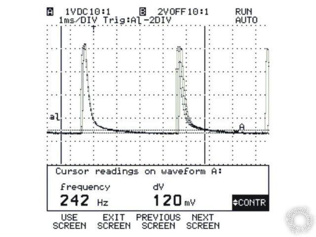
Went out & looked again on AC, and did see some activity, although it didn't appear to vary with the speed of the engine.  Took out the scope & took a pix (below).  When I press on the accelerometer, neither the pulse width nor the space between changes.

Last night I was looking at some other posts, and there was mention about a different tach line (I think it was a GREEN/ xxx wire somewhere near the hood release lever).  Is this still valid, or was it for an earlier version of the truck?  (I believe the post was for a 2007).

Thanks

ford 2008 f 350 avital 4103 , pkall - Page 2 -- posted image.

Tim
Page of 3

  Printable version Printable version Post ReplyPost New Topic
You cannot post new topics in this forum
You cannot reply to topics in this forum
You cannot delete your posts in this forum
You cannot edit your posts in this forum
You cannot create polls in this forum
You cannot vote in polls in this forum

  •  
Search the12volt.com
Follow the12volt.com Follow the12volt.com on Facebook
Friday, April 26, 2024 • Copyright © 1999-2024 the12volt.com, All Rights Reserved Privacy Policy & Use of Cookies
Disclaimer: *All information on this site ( the12volt.com ) is provided "as is" without any warranty of any kind, either expressed or implied, including but not limited to fitness for a particular use. Any user assumes the entire risk as to the accuracy and use of this information. Please verify all wire colors and diagrams before applying any information.

Secured by Sectigo
the12volt.com spacer
Support the12volt.com
Top
the12volt.com spacer