the12volt.com spacer
icon

Relay Diagram for Switching Polarity


Post ReplyPost New Topic
< Prev Topic Next Topic >
freewheelerrg 
Member - Posts: 2
Member spacespace
Joined: June 09, 2009
Location: Minnesota, United States
Posted: June 09, 2009 at 10:04 PM / IP Logged  
I need help configuring and setting up a relay(s) that will do the following.
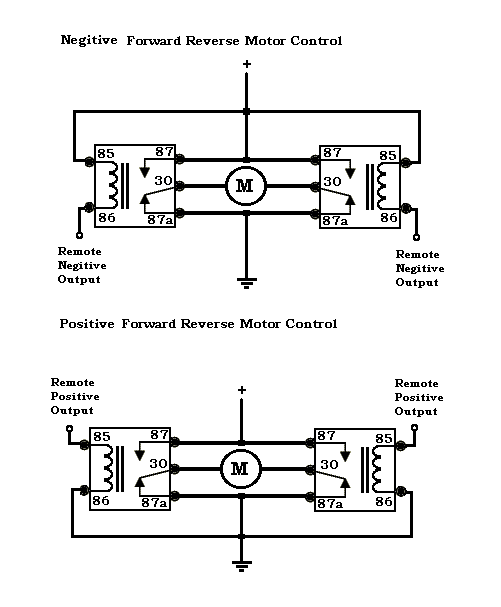
My 12 volt motor is normally off. When I push a 2 button remote control I want the first button to make the motor run clockwise. When I push the second button of the remote I want the motor to run counter-clockwise. How would I wire this and what type and how many relays would I need to accomplish this polarity switching?
Thanks in advance.
i am an idiot 
Platinum - Posts: 13,663
Platinum spaceThis member consistently provides reliable informationspace
Joined: September 21, 2006
Location: Louisiana, United States
Posted: June 09, 2009 at 10:46 PM / IP Logged  
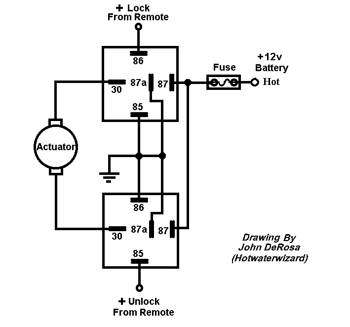
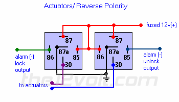
Scroll down to the diagram for Actuators/Reverse The 2 wires that are labeled to Actuators should now read to Motor. All other connections are labeled properly for your application.
hotwaterwizard 
Silver - Posts: 1,350
Silver spacespace
Joined: December 11, 2003
Location: California, United States
Posted: June 11, 2009 at 10:13 PM / IP Logged  

Relay Diagram for Switching Polarity -- posted image.

John DeRosa (Hotwaterwizard)
Stockton California
When in doubt, try it out !
i am an idiot 
Platinum - Posts: 13,663
Platinum spaceThis member consistently provides reliable informationspace
Joined: September 21, 2006
Location: Louisiana, United States
Posted: June 14, 2009 at 5:19 PM / IP Logged  

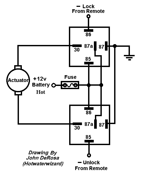
Most alarm outputs are negative.  The above diagram is designed to work with a positive out.   Following is the diagram I referenced earlier.  It uses a negative output to trigger it.  

Relay Diagram for Switching Polarity -- posted image.
hotwaterwizard 
Silver - Posts: 1,350
Silver spacespace
Joined: December 11, 2003
Location: California, United States
Posted: June 14, 2009 at 7:01 PM / IP Logged  

Whoopdie Do just switch around a couple of wires.

Relay Diagram for Switching Polarity -- posted image.

John DeRosa (Hotwaterwizard)
Stockton California
When in doubt, try it out !
i am an idiot 
Platinum - Posts: 13,663
Platinum spaceThis member consistently provides reliable informationspace
Joined: September 21, 2006
Location: Louisiana, United States
Posted: June 14, 2009 at 7:05 PM / IP Logged  
I am pretty sure that if he noticed that there was a problem with the setup, he probably would not have been here asking for help. 
freewheelerrg 
Member - Posts: 2
Member spacespace
Joined: June 09, 2009
Location: Minnesota, United States
Posted: June 15, 2009 at 10:40 AM / IP Logged  

Thanks for the info guys, it was very helpful. 

Just as an FYI on what I'm trying to do, this setup is for my boat lift.  I have a 12 Volt motor that I attached to the lift wheel and to move the lift up and down the motor just has the polarity reversed.  I want to be able to install a low volated remote control switch that I can operate from inside my boat while the 12 volt motor draws around 25 to 30 amps, thus the need for a relay.

i am an idiot 
Platinum - Posts: 13,663
Platinum spaceThis member consistently provides reliable informationspace
Joined: September 21, 2006
Location: Louisiana, United States
Posted: June 15, 2009 at 1:55 PM / IP Logged  

Depending on whether your remote device puts out a negative or a positive voltage, you have a diagram for each.  Good Luck and let us know how it works out.

hotwaterwizard 
Silver - Posts: 1,350
Silver spacespace
Joined: December 11, 2003
Location: California, United States
Posted: June 15, 2009 at 10:35 PM / IP Logged  

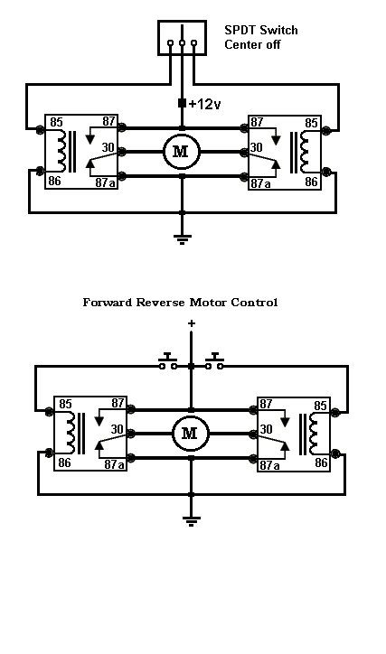
If you examine the circuits all 3 are basicly the same circuit with different hot and grounds. If you want the switch version here it is.

Relay Diagram for Switching Polarity -- posted image.

Relay Diagram for Switching Polarity -- posted image.

John DeRosa (Hotwaterwizard)
Stockton California
When in doubt, try it out !

Sorry, you can NOT post a reply.
This topic is closed.

  Printable version Printable version Post ReplyPost New Topic
You cannot post new topics in this forum
You cannot reply to topics in this forum
You cannot delete your posts in this forum
You cannot edit your posts in this forum
You cannot create polls in this forum
You cannot vote in polls in this forum

  •  
Search the12volt.com
Follow the12volt.com Follow the12volt.com on Facebook
Tuesday, March 19, 2024 • Copyright © 1999-2024 the12volt.com, All Rights Reserved Privacy Policy & Use of Cookies
Disclaimer: *All information on this site ( the12volt.com ) is provided "as is" without any warranty of any kind, either expressed or implied, including but not limited to fitness for a particular use. Any user assumes the entire risk as to the accuracy and use of this information. Please verify all wire colors and diagrams before applying any information.

Secured by Sectigo
the12volt.com spacer
Support the12volt.com
Top
the12volt.com spacer