the12volt.com spacer
icon

converting polarity issue


Post ReplyPost New Topic
< Prev Topic Next Topic >
KPierson 
Platinum - Posts: 3,527
Platinum spaceThis member consistently provides reliable informationspace
Joined: April 14, 2005
Location: Ohio, United States
Posted: January 04, 2011 at 11:09 AM / IP Logged  
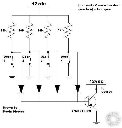
converting polarity issue - Page 2 -- posted image.
Kevin Pierson
scam404 
Copper - Posts: 113
Copper spacespace
Joined: November 07, 2009
Location: Virginia, United States
Posted: January 04, 2011 at 11:59 AM / IP Logged  
Kevin,
Thanks a lot for that diagram. I have never used a transistor before, but I have been reading about them and they do not seem to be too difficult. I imagine in this case I will not be amplifying any signal but instead just using the transistor as a switch. On your diagram at the bottom you show the output as a negative out, but you have it labeled as 12 VDC, are you just saying that it is a ground output? Also, on my install I diode isolated all four of the door triggers, but I do not see any diodes on your diagram, that will not make a difference will it?
KPierson 
Platinum - Posts: 3,527
Platinum spaceThis member consistently provides reliable informationspace
Joined: April 14, 2005
Location: Ohio, United States
Posted: January 04, 2011 at 12:53 PM / IP Logged  

The diodes are there - they are the black triangles before all four switches come together.

The transistor collector should NOT be connected to 12vdc.  I'm not sure why I did that.  That (-) output should be connected directly to the (-) input of the alarm and voice module.

Make sure you connect the emitter of the transistor to ground, the base to the output of all 4 doors, and the collector to the inputs of the devices.  Should be pretty easy.

Kevin Pierson
howie ll 
Pot Metal - Posts: 16,466
Pot Metal spacespace
Joined: January 09, 2007
Location: United Kingdom
Posted: January 04, 2011 at 12:53 PM / IP Logged  
Scam, the diodes are represented by the arrows at bottom going to the transistor.
The bands would be towards the transistor.
I agree with your polarity comment, what's the answer KP?
howie ll 
Pot Metal - Posts: 16,466
Pot Metal spacespace
Joined: January 09, 2007
Location: United Kingdom
Posted: January 04, 2011 at 12:55 PM / IP Logged  
Sorry, KP, bad timing.
scam404 
Copper - Posts: 113
Copper spacespace
Joined: November 07, 2009
Location: Virginia, United States
Posted: January 04, 2011 at 12:58 PM / IP Logged  
thanks a lot guys, this forum is awesome. I am actually getting to use some of the crap I am learning about in my electrical engineering classes.
oldspark 
Gold - Posts: 4,913
Gold spacespace
Joined: November 03, 2008
Location: Australia
Posted: January 04, 2011 at 3:01 PM / IP Logged  
I presume the output's input has a pull-up resistor etc? (IE - In KP's tranny diagram. That's a classic "open collector" output - great stuff - the "universal interface solution".)
I also note a lack of base resistor... Base current will vary 4-fold depending on how many switches are open.... OH NO IT WON'T! Geez there are some idiots on this forum!   Base current will be via 2.5k else nothing. (~12V/2k5 ~5mA)
See - I knew KP was right!
... Though I was going to suggest a FET to overcome that - ie, "base" = gate current irrelevant (nA or uA), merely its gate voltage higher than about 5V to turn on, but must be pulled low for off (normally a resistor as with a transistor, but 1M etc - but not needed in this case because either a switch pulls it to ground else dosn't.
Of course one wonders how those diodes will pull the base or gate down to 0V/GND with that orientation - but maybe I am the "one" that wonders that?
I'd have them the other way with a single base/gate resistor to +12V (eg, 2.5k => 2.2k or 2.7k etc, or 1M (or 1k to 10M) for the FET)....
But it is before 8AM here.... (and I skipped the switch resistance detail).   
And of course, only "the first" door triggers, and last door "resets" - ie, the change occurs between all closed and [any or all] open.
Coffee time.... Then maybe a second laugh at some nameless dork, else maybe a chance to redeem mys... him/herself. (I'll bet the former...)
(More) Trivial FYI only:
scam404 wrote:
I am actually getting to use some of the crap I am learning about in my electrical engineering classes.
WHAT?
It wasn't until 3rd year that happened to me - and that was merely finding out that by moving the fast brush closer to the ground brush in my wiper motor, I would have a reasonable high speed instead of "slow plus stuff all".
Mind you - I was totally rapt. It took 3 years, but I finally learned something practical.
Compare that to second year where I had a lecturer removed when he suggested the LM317 adjustable 3 terminal voltage regulator was "probably" adjusted with a screw driver.... and that was for a practical "Design" class lab-prac! (Actually I let that one go. I had him removed later when - in his other "theoretical" Electronics class - he scoffed at those that couldn't "design" as simple 2 stage tranny amp (but with DC coupling!). Yet neither could he as we later confirmed. That was an other implementation of what some knew or now know as "DFWAA". I won't mention the other times, but I strongly suggest you "go with the masses" - never EVER correct long erred beliefs or prac class results - let others do that. But it was good training for real life LOL!)   
Sorry - I love formal education and qualifications as you may well be aware. (Experience - just get that from a book or school. My old uni still uses the latest in SSL2 protocols and new yet disparit(??) IT systems with manual transfers - of REPEAT info! But my later uni now allows working in groups and does not consider it "cheating"! Masters of F-wits those Degrees!)
KPierson 
Platinum - Posts: 3,527
Platinum spaceThis member consistently provides reliable informationspace
Joined: April 14, 2005
Location: Ohio, United States
Posted: January 04, 2011 at 3:17 PM / IP Logged  

I run much higher resistances through a diode though the base of a 3904 with no issues (as high as 1.5 megaohm).  Because the transistor is only a switch the changing of the base resistance won't matter. 

The alarm inputs should have pull ups on them as most car alarms are NO and go to ground when door is closed.  This, is theory, of course, and a 10K resistor can be placed between the (-) output and 12vdc if there are any issues.

Kevin Pierson
scam404 
Copper - Posts: 113
Copper spacespace
Joined: November 07, 2009
Location: Virginia, United States
Posted: January 04, 2011 at 4:00 PM / IP Logged  
Ok I just got done installing the transistor, and everything works perfectly now. That thing was a real pain to solder to the individual wires though. Is there some way I dont know about to solder those things? It looks like it is meant for circuit board use only... I had to CAREFULLY put tiny pieces of electrical tape on each one to keep them from touching.
KPierson 
Platinum - Posts: 3,527
Platinum spaceThis member consistently provides reliable informationspace
Joined: April 14, 2005
Location: Ohio, United States
Posted: January 04, 2011 at 4:06 PM / IP Logged  
I would have bought a little prototype board and soldered it ot that, then soldered the wires to the bottom of the board.  If you solder directly to the pins and make sure all the wires are taped together so no individual leg can be pulled off you'll be ok.  Alternatively, you could have went with a much larger NPN transistor that is available in a TO220 package - a little friendlier then the TO92 package.
Kevin Pierson
Page of 5

  Printable version Printable version Post ReplyPost New Topic
You cannot post new topics in this forum
You cannot reply to topics in this forum
You cannot delete your posts in this forum
You cannot edit your posts in this forum
You cannot create polls in this forum
You cannot vote in polls in this forum

  •  
Search the12volt.com
Follow the12volt.com Follow the12volt.com on Facebook
Wednesday, May 15, 2024 • Copyright © 1999-2024 the12volt.com, All Rights Reserved Privacy Policy & Use of Cookies
Disclaimer: *All information on this site ( the12volt.com ) is provided "as is" without any warranty of any kind, either expressed or implied, including but not limited to fitness for a particular use. Any user assumes the entire risk as to the accuracy and use of this information. Please verify all wire colors and diagrams before applying any information.

Secured by Sectigo
the12volt.com spacer
Support the12volt.com
Top
the12volt.com spacer