the12volt.com spacer
icon

hornet 570t remote start


Post ReplyPost New Topic
< Prev Topic Next Topic >
howie ll 
Pot Metal - Posts: 16,466
Pot Metal spacespace
Joined: January 09, 2007
Location: United Kingdom
Posted: June 10, 2012 at 5:32 PM / IP Logged  
Check to see if you've shorted that white wire to ground.
1997gmcyukon 
Member - Posts: 16
Member spacespace
Joined: June 10, 2012
Location: Louisiana, United States
Posted: June 10, 2012 at 5:41 PM / IP Logged  

Howie,

Don't understand what you mean.  I did change the fuse to set in the + slot and it seems to be fine.  Now changing the white wire to tie in to the brown wire behind the light switch. 

1997gmcyukon 
Member - Posts: 16
Member spacespace
Joined: June 10, 2012
Location: Louisiana, United States
Posted: June 10, 2012 at 5:47 PM / IP Logged  

Howie,

Is it possible for me to use a relay instead of the DEI 451?  I have two on hand and wasn't sure or should I go source out the right part tomorrow.  Just trying to finish up.  (The two relays I have are: 12V  20/30A Tyco relays - 5 prong)

If yes then I need some help wiring up relays.  Never used before.

Thanks again for your help.

1997gmcyukon 
Member - Posts: 16
Member spacespace
Joined: June 10, 2012
Location: Louisiana, United States
Posted: June 10, 2012 at 6:55 PM / IP Logged  

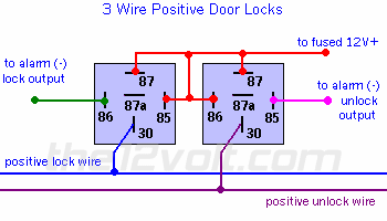
Is it possible for me to use the diagram below with two relays instead of the DEI 451m?????????

hornet 570t remote start - Page 2 -- posted image.

howie ll 
Pot Metal - Posts: 16,466
Pot Metal spacespace
Joined: January 09, 2007
Location: United Kingdom
Posted: June 10, 2012 at 6:58 PM / IP Logged  
Go to the relay section on this site and look up 5 wire or this diagram:- type_c_locks.bmp
Fuse and diodes are mandatory
howie ll 
Pot Metal - Posts: 16,466
Pot Metal spacespace
Joined: January 09, 2007
Location: United Kingdom
Posted: June 10, 2012 at 7:00 PM / IP Logged  
That diagram is correct but mine will save you from frying your alarm.
1997gmcyukon 
Member - Posts: 16
Member spacespace
Joined: June 10, 2012
Location: Louisiana, United States
Posted: June 10, 2012 at 7:06 PM / IP Logged  

Howie,

I can't thank you enough for all your help.  God bless.

Thanks,

___________________________________

This web site is the bomb.

kreg357 
Platinum - Posts: 7,789
Platinum spaceThis member has made a donation to the12volt.com. Click here for more info.spaceThis member has been recognized as an authority in Electrical Theory. Click here for more info.spaceThis member has been recognized as an authority in Mobile Security and Convenience. Click here for more info.spacespace
Joined: January 30, 2009
Location: Pennsylvania, United States
Posted: June 10, 2012 at 8:19 PM / IP Logged  

Minor update to Howards Type C lock diagram link above.  Also connect Pin 87 of the right relay ( Unlock ) to +12V.

Here is a link to the DEI 451M Install guide :  https://www.the12volt.com/installbay/file.asp?ID=726

Follow the Type C guide to test and determine correct vehicle connections.

Soldering is fun!
1997gmcyukon 
Member - Posts: 16
Member spacespace
Joined: June 10, 2012
Location: Louisiana, United States
Posted: June 10, 2012 at 9:53 PM / IP Logged  

Thanks Kreg357.

Appreciate all your help.

howie ll 
Pot Metal - Posts: 16,466
Pot Metal spacespace
Joined: January 09, 2007
Location: United Kingdom
Posted: June 11, 2012 at 5:03 AM / IP Logged  
Oops, sorry about the error, it was 1:20am here.
Page of 3

  Printable version Printable version Post ReplyPost New Topic
You cannot post new topics in this forum
You cannot reply to topics in this forum
You cannot delete your posts in this forum
You cannot edit your posts in this forum
You cannot create polls in this forum
You cannot vote in polls in this forum

  •  
Search the12volt.com
Follow the12volt.com Follow the12volt.com on Facebook
Sunday, May 19, 2024 • Copyright © 1999-2024 the12volt.com, All Rights Reserved Privacy Policy & Use of Cookies
Disclaimer: *All information on this site ( the12volt.com ) is provided "as is" without any warranty of any kind, either expressed or implied, including but not limited to fitness for a particular use. Any user assumes the entire risk as to the accuracy and use of this information. Please verify all wire colors and diagrams before applying any information.

Secured by Sectigo
the12volt.com spacer
Support the12volt.com
Top
the12volt.com spacer