the12volt.com spacer
icon

hornet 570t remote start


Post ReplyPost New Topic
< Prev Topic Next Topic >
1997gmcyukon 
Member - Posts: 16
Member spacespace
Joined: June 10, 2012
Location: Louisiana, United States
Posted: June 13, 2012 at 7:54 AM / IP Logged  

Good Morning,

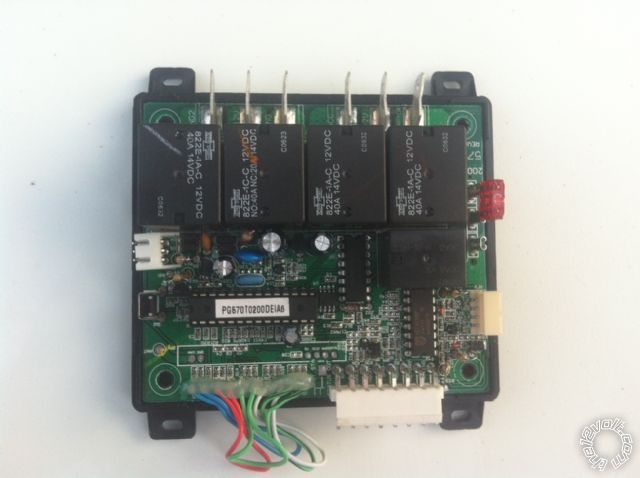
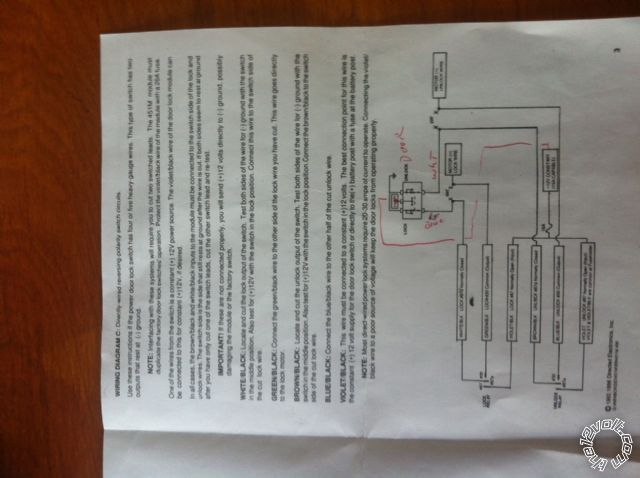
I have recently installed a HORNET 570T remote start and door lock/unlock in a 1997 GMC Yukon 2/door.  The remote start is working fine but having trouble with the door locks and programming my remote.  I had to add a DEI 451 Micro doorlock relay module. I am indicating that I have Type C door lock circuits. Directly wired (no factory relays) reversing polarity switches???  So I used the wiring diagram "c" that came with the relay.  Tried to activate the doors and I can here the signal in module but the doors are not locking/unlocking.  Is there a way to check to see if I am getting a signal coming out of the module??hornet 570t remote start - Page 3 -- posted image.

1997gmcyukon 
Member - Posts: 16
Member spacespace
Joined: June 10, 2012
Location: Louisiana, United States
Posted: June 13, 2012 at 8:31 AM / IP Logged  
These diagrams are what I am going by:
hornet 570t remote start - Page 3 -- posted image.
1997gmcyukon 
Member - Posts: 16
Member spacespace
Joined: June 10, 2012
Location: Louisiana, United States
Posted: June 13, 2012 at 8:33 AM / IP Logged  
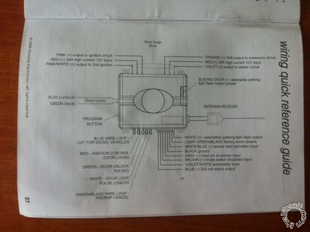
hornet 570t remote start - Page 3 -- posted image.
1997gmcyukon 
Member - Posts: 16
Member spacespace
Joined: June 10, 2012
Location: Louisiana, United States
Posted: June 13, 2012 at 8:41 AM / IP Logged  

When I push on the remote the box (module) receives the signal.  I can here it clicking.  Just not sure how to check if the signal is leaving the box to the doors??and what voltage should I see if any.

*Blue wire indicates a (-) unlock and green wire indicates (-) lock.  I disconnected the plug and tested the blue and green wire with my meter. I engage the remote while still plugged to my meter and get nothing leaving the module?

howie ll 
Pot Metal - Posts: 16,466
Pot Metal spacespace
Joined: January 09, 2007
Location: United Kingdom
Posted: June 13, 2012 at 9:53 AM / IP Logged  
First test at the 570t.
Use a DMM, red probe to power source and black to each wire.
Connect to blue, on arming you should get 12V+ momentarily.
Connect to blue, disarm should be the same.
That tells you the 570t is OK.
Is this a 2 door or 4?
If 2 wire as follows; if there's a switch in both doors, use the passenger door switch and follow this diagram.
yukon_lock.bmp
If it's a 4 door take the first diagram, turn the diodes round and connect directly.
kreg357 
Platinum - Posts: 7,789
Platinum spaceThis member has made a donation to the12volt.com. Click here for more info.spaceThis member has been recognized as an authority in Electrical Theory. Click here for more info.spaceThis member has been recognized as an authority in Mobile Security and Convenience. Click here for more info.spacespace
Joined: January 30, 2009
Location: Pennsylvania, United States
Posted: June 13, 2012 at 10:09 AM / IP Logged  

Info for 2 Door vehicle with Type C locks...

Verify +12V at 451M module side of the 15mp fuse in the Purple,

PURPLE / Black wire.  ( Also verifies fuse. )

Verify +12V output on 451M Module GREEN/ Black wire with Lock command.

Verify +12V output on 451M Module Blue/Black wire with UnLock command.

Another test.  Disconnect the White 3 Pin plug between the 451M and the

Hornet.  Apply +12V to the center Red wire, then briefly ground either
the Blue or Green wire to simulate a lock or unlock command.

One possibility, 451M output wires are reversed on the cut Lock and Unlock

vehicle wire.  The install guide describes the test procedure to identify
the correct wiring connections.

Soldering is fun!
1997gmcyukon 
Member - Posts: 16
Member spacespace
Joined: June 10, 2012
Location: Louisiana, United States
Posted: June 13, 2012 at 11:19 AM / IP Logged  

Thanks again Howie and Kreg.  Will try that.

Page of 3

Sorry, you can NOT post a reply.
This topic is closed.

  Printable version Printable version Post ReplyPost New Topic
You cannot post new topics in this forum
You cannot reply to topics in this forum
You cannot delete your posts in this forum
You cannot edit your posts in this forum
You cannot create polls in this forum
You cannot vote in polls in this forum

  •  
Search the12volt.com
Follow the12volt.com Follow the12volt.com on Facebook
Sunday, May 19, 2024 • Copyright © 1999-2024 the12volt.com, All Rights Reserved Privacy Policy & Use of Cookies
Disclaimer: *All information on this site ( the12volt.com ) is provided "as is" without any warranty of any kind, either expressed or implied, including but not limited to fitness for a particular use. Any user assumes the entire risk as to the accuracy and use of this information. Please verify all wire colors and diagrams before applying any information.

Secured by Sectigo
the12volt.com spacer
Support the12volt.com
Top
the12volt.com spacer