the12volt.com spacer
icon

python 5706 door locks


Post ReplyPost New Topic
< Prev Topic Next Topic >
freqsounds 
Copper - Posts: 289
Copper spacespace
Joined: October 17, 2008
Location: Virginia, United States
Posted: March 01, 2014 at 9:23 AM / IP Logged  
With your red probe on a +12V constant source, and the black probe on the lock or unlock wire from the alarm, you should see it spike to 12V. The output duration of the pulse is usually .4 seconds by default.
After the relays are hooked up, both wires going to the actuator should be ground when not being sent a signal. When a lock or unlock signal is sent from the alarm, the relay should output a +12V pulse on one of the wires to the actuator.
Hope that makes sense!
No question is stupid or not worth asking. You were once a noob, right? :)
hoe_nah808 
Member - Posts: 27
Member spacespace
Joined: February 12, 2014
Location: Hawaii, United States
Posted: March 01, 2014 at 2:07 PM / IP Logged  
freqsounds wrote:
With your red probe on a +12V constant source, and the black probe on the lock or unlock wire from the alarm, you should see it spike to 12V. The output duration of the pulse is usually .4 seconds by default.
After the relays are hooked up, both wires going to the actuator should be ground when not being sent a signal. When a lock or unlock signal is sent from the alarm, the relay should output a +12V pulse on one of the wires to the actuator.
Hope that makes sense!
okay thanks that makes a lot of sense to me know haha..thanks for the help..going to try this out before i head off to work today
hoe_nah808 
Member - Posts: 27
Member spacespace
Joined: February 12, 2014
Location: Hawaii, United States
Posted: March 01, 2014 at 3:01 PM / IP Logged  
okay went out and found this.
using my dmm red wire on a constant 12v black wire to the alarm it will read 12v. when I click the lock/unlock button voltage drops.
on the relay
87 reads 12v
86/85 12v
86/85 going to the alarm reads 9v
30 reads 0.
when I lock/unlock from my remote pin 30 doesnt recieve any power at all. tried grounding 87a and still nothing on both of my relays.
freqsounds 
Copper - Posts: 289
Copper spacespace
Joined: October 17, 2008
Location: Virginia, United States
Posted: March 01, 2014 at 4:02 PM / IP Logged  
85 and 86 are not the same terminals. They are the coil terminals. To make the relay trip, one needs ground and the other needs +12V. If they're both reading the same, disconnect the wires from the relay then meter. Pin 85 should have the ground feed from the alarm, and 86 should have the (+) constant feed with a diode connected from 85 to 86 with the band side on pin 86.
If your relays have diodes, this is probably why it's not working. The diagram at https://www.the12volt.com/doorlocks/page3.asp#arp has no diodes in the diagram. If both of your relays have diodes, switch 85 and 86 on relay 1.
You're using the blue and green wires from the alarm, right? The ones on the 3 pin connector?
It may be easier at this point to tear down the relays and use the diagram in the link above. Pay special attention to what I said about relay 1.
No question is stupid or not worth asking. You were once a noob, right? :)
hoe_nah808 
Member - Posts: 27
Member spacespace
Joined: February 12, 2014
Location: Hawaii, United States
Posted: March 01, 2014 at 4:14 PM / IP Logged  
yup green and blue from the alarm. gonna spend my day at work trying to figure out this relay situation.
hoe_nah808 
Member - Posts: 27
Member spacespace
Joined: February 12, 2014
Location: Hawaii, United States
Posted: March 01, 2014 at 4:19 PM / IP Logged  
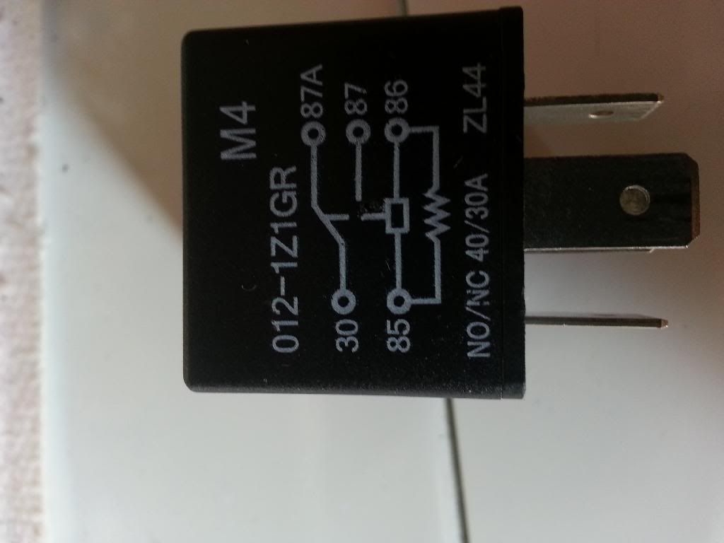
python 5706 door locks - Page 2 -- posted image.
freqsounds 
Copper - Posts: 289
Copper spacespace
Joined: October 17, 2008
Location: Virginia, United States
Posted: March 01, 2014 at 4:23 PM / IP Logged  
Yea, there's a diode built in. That's what that zigzag line is across 85 and 86.
No question is stupid or not worth asking. You were once a noob, right? :)
freqsounds 
Copper - Posts: 289
Copper spacespace
Joined: October 17, 2008
Location: Virginia, United States
Posted: March 01, 2014 at 4:24 PM / IP Logged  
Correction:that's a resistor. Not a diode.
No question is stupid or not worth asking. You were once a noob, right? :)
freqsounds 
Copper - Posts: 289
Copper spacespace
Joined: October 17, 2008
Location: Virginia, United States
Posted: March 01, 2014 at 4:32 PM / IP Logged  
So this has a similar effect of a diode without the unidirectional effect of the voltage.
Try this: take just the (-) trigger and put it on pin 85. Connect 86 to +12V and leave the other terminals connected. Press the lock or unlock button and listen for a click from the relay. If it doesn't click, you'll probably need different relays.
No question is stupid or not worth asking. You were once a noob, right? :)
hoe_nah808 
Member - Posts: 27
Member spacespace
Joined: February 12, 2014
Location: Hawaii, United States
Posted: March 03, 2014 at 5:17 PM / IP Logged  
okay the relays work thats for sure. I put 12v to the 85 and grounded the 86 via chassis ground and the relay clicks. BUT im still not getting anywhere
85 constant 12v
86 ground from alarm GREEN/ blue harness
when I get my multimeter and put the red wire to the 86 pin and black wire to chassis ground I get a reading of 9volts. when I hit my lock button it jumps to 10volts. when I hit unlock itll drop to 7v.
doing this the relay DOES NOT click on or off. all the other wires are not connected
87 pin 12v
87a ground
with my dmm and the 85/86 pins hooked up the 30 pin turns into a ground on both of my relays. when I click the lock or unlock on my remote for my alarm nothing happens no jump/spike in pin 30. when I remove 87a from being grounded, nothing happens to the 30pin. its not a ground and no jump#spike in voltage.
these are all new relays...not sure where to go from here
Page of 7

  Printable version Printable version Post ReplyPost New Topic
You cannot post new topics in this forum
You cannot reply to topics in this forum
You cannot delete your posts in this forum
You cannot edit your posts in this forum
You cannot create polls in this forum
You cannot vote in polls in this forum

  •  
Search the12volt.com
Follow the12volt.com Follow the12volt.com on Facebook
Thursday, May 9, 2024 • Copyright © 1999-2024 the12volt.com, All Rights Reserved Privacy Policy & Use of Cookies
Disclaimer: *All information on this site ( the12volt.com ) is provided "as is" without any warranty of any kind, either expressed or implied, including but not limited to fitness for a particular use. Any user assumes the entire risk as to the accuracy and use of this information. Please verify all wire colors and diagrams before applying any information.

Secured by Sectigo
the12volt.com spacer
Support the12volt.com
Top
the12volt.com spacer