the12volt.com spacer
icon

Viper 5706v install 2005 Silverado ex cab


Post ReplyPost New Topic
< Prev Topic Next Topic >
kreg357 
Platinum - Posts: 7,783
Platinum spaceThis member has made a donation to the12volt.com. Click here for more info.spaceThis member has been recognized as an authority in Electrical Theory. Click here for more info.spaceThis member has been recognized as an authority in Mobile Security and Convenience. Click here for more info.spacespace
Joined: January 30, 2009
Location: Pennsylvania, United States
Posted: March 13, 2017 at 8:47 PM / IP Logged Link to Post Post Reply Quote kreg357
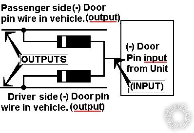
Here is the rear door pin isolation wiring using two 1N4004 diodes. If you were going W2W, you could add the FLCAN front door trigger output to this and input all three signal to the Vipers (-) Door Trigger input wire.
Viper 5706v install 2005 Silverado ex cab - Page 6 -- posted image.
Soldering is fun!
vital_idol 
Member - Posts: 19
Member spacespace
Joined: March 06, 2017
Location: Texas, United States
Posted: March 14, 2017 at 2:48 PM / IP Logged Link to Post Post Reply Quote vital_idol
so everything is wired up and i tried testing. RS fails and i get 8 flashes on brake lights. I
according to viper doc, it says that means wire 13 isn't grounded. I have double checked that it is.
Any suggestions?
I was getting 7 flashes, found that meant manual transmission mode, followed instructions to set to automatic, now i get the 8 flashes.
vital_idol 
Member - Posts: 19
Member spacespace
Joined: March 06, 2017
Location: Texas, United States
Posted: March 14, 2017 at 2:56 PM / IP Logged Link to Post Post Reply Quote vital_idol
ok i'm dumb. Guess I didn't understand the instructions. I did not attach the neutral safety switch. attached that and it works now.
Can anyone explain what that switch is for?
vital_idol 
Member - Posts: 19
Member spacespace
Joined: March 06, 2017
Location: Texas, United States
Posted: March 14, 2017 at 3:18 PM / IP Logged Link to Post Post Reply Quote vital_idol
so now i'm on the last thing before clean up / completion.
The rear door triggers. I've seen multiple postings that say same thing, about them being on a purple or violet plug at BCM. I don't have a purple plug, or I am looking in the wrong place.
NOTE #5: On BASE Model trucks, the Door Trigger wires are @ the BCM, LT BLUE PLUG, PINS B4 and A5. On 4-Door Trucks the LEFT REAR Door is a LT BLUE/BLACK (-) PIN A3 and the RIGHT REAR Door is a LT GREEN/BLACK (-) PIN A2, located in a PURPLE PLUG at the BCM, use all 4 wires and diode isolate when installing an alarm system.
These notes always say BASE model, if my truck is an LS, would the same wiring apply?
vital_idol 
Member - Posts: 19
Member spacespace
Joined: March 06, 2017
Location: Texas, United States
Posted: March 14, 2017 at 3:19 PM / IP Logged Link to Post Post Reply Quote vital_idol
ok found a note that says purple plug is on the back of BCM. I'll take a look. Thanks everyone!
vital_idol 
Member - Posts: 19
Member spacespace
Joined: March 06, 2017
Location: Texas, United States
Posted: March 14, 2017 at 3:53 PM / IP Logged Link to Post Post Reply Quote vital_idol
found the door wires.
Now it appears my ignorance has no bounds...   box says this alarm comes with a status LED. I'm not seeing any type of status LED to install. I'm thinking of the blinking light I use to see in dash boards. Is there supposed to be one? Didn't notice any mention of it in wiring info.
vital_idol 
Member - Posts: 19
Member spacespace
Joined: March 06, 2017
Location: Texas, United States
Posted: March 14, 2017 at 3:54 PM / IP Logged Link to Post Post Reply Quote vital_idol
perhaps its the LED on the control center/antenna?
kreg357 
Platinum - Posts: 7,783
Platinum spaceThis member has made a donation to the12volt.com. Click here for more info.spaceThis member has been recognized as an authority in Electrical Theory. Click here for more info.spaceThis member has been recognized as an authority in Mobile Security and Convenience. Click here for more info.spacespace
Joined: January 30, 2009
Location: Pennsylvania, United States
Posted: March 14, 2017 at 4:32 PM / IP Logged Link to Post Post Reply Quote kreg357
vital_idol wrote:
perhaps its the LED on the control center/antenna?
Yes, on the antenna.
Soldering is fun!
kreg357 
Platinum - Posts: 7,783
Platinum spaceThis member has made a donation to the12volt.com. Click here for more info.spaceThis member has been recognized as an authority in Electrical Theory. Click here for more info.spaceThis member has been recognized as an authority in Mobile Security and Convenience. Click here for more info.spacespace
Joined: January 30, 2009
Location: Pennsylvania, United States
Posted: March 14, 2017 at 4:35 PM / IP Logged Link to Post Post Reply Quote kreg357
vital_idol wrote:
ok i'm dumb. Guess I didn't understand the instructions. I did not attach the neutral safety switch. attached that and it works now.
Can anyone explain what that switch is for?
The Neutral Safety switch is another way to disable the remote start function. Think of it as a safety switch for when you are having the truck serviced. The Hood Pin should be enough but it is extra protection.
Soldering is fun!
vital_idol 
Member - Posts: 19
Member spacespace
Joined: March 06, 2017
Location: Texas, United States
Posted: March 14, 2017 at 7:44 PM / IP Logged Link to Post Post Reply Quote vital_idol
all done!!   
Thanks for all the help everyone!   Kreg357, thank you for the specifics on the door wiring and answers to the relay questions.
Everything appears to work and even was able to make the safety switch non-visible but easily accessible.   
No extra screws left after putting dash back together, always a plus.
I would never choose to solder 12 gauge wires to each other again. That was time consuming.
Page of 6

If you wish to post a reply to this topic, you must first login.
If you are not already registered, you must first register.

  Printable version Printable version Post ReplyPost New Topic
You cannot post new topics in this forum
You cannot reply to topics in this forum
You cannot delete your posts in this forum
You cannot edit your posts in this forum
You cannot create polls in this forum
You cannot vote in polls in this forum

  •  
Search the12volt.com
Follow the12volt.com Follow the12volt.com on Facebook
Friday, April 26, 2024 • Copyright © 1999-2024 the12volt.com, All Rights Reserved Privacy Policy & Use of Cookies
Disclaimer: *All information on this site ( the12volt.com ) is provided "as is" without any warranty of any kind, either expressed or implied, including but not limited to fitness for a particular use. Any user assumes the entire risk as to the accuracy and use of this information. Please verify all wire colors and diagrams before applying any information.

Secured by Sectigo
the12volt.com spacer
Support the12volt.com
Top
the12volt.com spacer