the12volt.com spacer
icon

Remote Start Anti-Grind


Post ReplyPost New Topic
< Prev Topic Next Topic >
MaxV6 
Member - Posts: 22
Member spacespace
Joined: January 08, 2003
Location: Canada
Posted: January 05, 2004 at 5:17 PM / IP Logged  

How do you guys create an anit-grind circuit if the RS unit does not have it built in.

I know I can use the starter kill relay for this but I don't know where to get a constant power (-) or (+) only when the RS is active. I was thinking of the TACH if there is enough to power a relay but then that will always be active when the engine is running and not only in RS mode.

Why don't car manufacturers make this a standard feature?

LittleBill 
Copper - Posts: 72
Copper spacespace
Joined: May 16, 2003
Location: United States
Posted: January 05, 2004 at 5:32 PM / IP Logged  
um i bought a piece of crap one from walmart, bulldog works flawless, doesn't have anti grind, but anyway, use the wire for passlock feature, it throws a steady negative output, till the rs is disabled, perfect for anti grind
MaxV6 
Member - Posts: 22
Member spacespace
Joined: January 08, 2003
Location: Canada
Posted: January 05, 2004 at 8:41 PM / IP Logged  

LittleBill wrote:
um i bought a piece of crap one from walmart, bulldog works flawless, doesn't have anti grind, but anyway, use the wire for passlock feature, it throws a steady negative output, till the rs is disabled, perfect for anti grind

Thanks LittleBill, I have to find a similar wire on my RS unit.

superchuckles 
Copper - Posts: 89
Copper spacespace
Joined: December 29, 2003
Location: United States
Posted: January 12, 2004 at 9:19 AM / IP Logged  

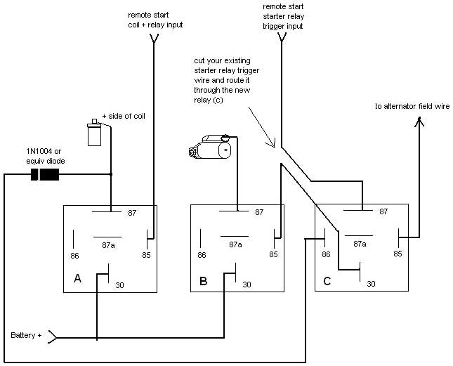
try doing this - for the anti-grind, tie a wire from your relay providing power to the coil, to pin 85 of a new relay, then wire pin 86 of the new relay to your alternators field wire.  when your relay provides power for the coil, it will energize the new relay, and you should route your starter relays power thru the new relay.  bah - i'll draw ya a diagram.....

Remote Start Anti-Grind -- posted image.

A = your existing remote start coil power relay

B = your existing remote start starter motor power relay

C = New anti-grind relay

how it works - when the engine is not running, the field wire on the alternator will provide the ground necessary to activate relay C when there is power applied to the coil by relay A.  that will complete your starter circuit to the way you have it now, but - once the engine has started, the alternator field wire will change to a + output.  since there will be + on both 85 and 86 of relay C, the relay will shut off,  breaking the circuit so that relay B cannot be energized again until such time as the engine dies.   by the way, just about any general purpose diode will work, and you have to have it.  if you just wire it without the diode, the field wire could provide enough power thru the relay to keep your engine running (though not completely likely, i have seen it happen).  hope this helps

HamiltonAudio 
Silver - Posts: 278
Silver spacespace
Joined: October 15, 2003
Posted: January 13, 2004 at 10:12 AM / IP Logged  

or you can just use one relay in a starter kill/anti grind configuration, have it done in 5 minutes and get the customer out the door  Remote Start Anti-Grind -- posted image.

b

defective 
Silver - Posts: 642
Silver spacespace
Joined: August 20, 2003
Location: Canada
Posted: January 13, 2004 at 10:34 AM / IP Logged  
yup....use a negative when running wire to cut the starter wire (obviously connect the RS starter wire on the starter motor side of this relay)

Sorry, you can NOT post a reply.
This topic is closed.

  Printable version Printable version Post ReplyPost New Topic
You cannot post new topics in this forum
You cannot reply to topics in this forum
You cannot delete your posts in this forum
You cannot edit your posts in this forum
You cannot create polls in this forum
You cannot vote in polls in this forum

  •  
Search the12volt.com
Follow the12volt.com Follow the12volt.com on Facebook
Friday, May 10, 2024 • Copyright © 1999-2024 the12volt.com, All Rights Reserved Privacy Policy & Use of Cookies
Disclaimer: *All information on this site ( the12volt.com ) is provided "as is" without any warranty of any kind, either expressed or implied, including but not limited to fitness for a particular use. Any user assumes the entire risk as to the accuracy and use of this information. Please verify all wire colors and diagrams before applying any information.

Secured by Sectigo
the12volt.com spacer
Support the12volt.com
Top
the12volt.com spacer