


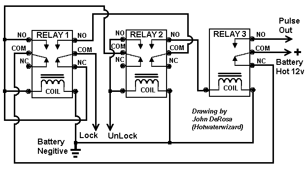
Three Pulses converted to one pulse


Posted: October 28, 2004 at 5:35 PM / IP Logged


Posted: October 30, 2004 at 9:51 PM / IP Logged
Posted: November 02, 2004 at 11:06 AM / IP Logged
Posted: November 02, 2004 at 4:55 PM / IP Logged
Posted: November 03, 2004 at 10:44 AM / IP Logged
Posted: November 03, 2004 at 6:58 PM / IP Logged
Posted: November 03, 2004 at 7:13 PM / IP Logged

Posted: November 04, 2004 at 3:27 PM / IP Logged
Posted: November 04, 2004 at 9:22 PM / IP Logged

Posted: November 05, 2004 at 2:00 AM / IP Logged
 Questions for installers who know how to work with our TR-7: I'm designing a more advanced TR-7 (TR-8?, I have not decided what part #)with more trigger inputs. It may have 2 to 4 separate trigger inputs and maybe 4 to 6 outputs. It is going to be designed more for installer side than consumer because a programmer is going to be needed, which will use a laptop/desktop as the GUI. So what i like to know is what would you like to see in the TR-8? Is there something that is needed that the TR-7 did not cover?
 Printable version
| You cannot post new topics in this forum You cannot reply to topics in this forum You cannot delete your posts in this forum You cannot edit your posts in this forum You cannot create polls in this forum You cannot vote in polls in this forum |

| Search the12volt.com |
Follow the12volt.com 
Wednesday, May 15, 2024 • Copyright © 1999-2024 the12volt.com, All Rights Reserved • Privacy Policy & Use of Cookies

Wednesday, May 15, 2024 • Copyright © 1999-2024 the12volt.com, All Rights Reserved • Privacy Policy & Use of Cookies
Disclaimer:
*All information on this site ( the12volt.com ) is provided "as is" without any warranty of any kind, either expressed or implied, including but not limited to fitness for a particular use. Any user assumes the entire risk as to the accuracy and use of this information. Please
verify all wire colors and diagrams before applying any information.
