the12volt.com spacer
icon

97 Prelude, Autopage


Post ReplyPost New Topic
< Prev Topic Next Topic >
cleanlude 
Member - Posts: 19
Member spacespace
Joined: May 09, 2005
Posted: May 10, 2005 at 10:20 AM / IP Logged  

Hey,

what's the best spot to pass the power wire through the firewall of my 97 Prelude. I see a rubber grommet thing on the passenger side, but it looks sealed quite well and I don't like cutting into it, unless it's my only option.


I'd like to avoid drilling if possible aswell... Any info or help appreciated!

Thanks

cleanlude 
Member - Posts: 19
Member spacespace
Joined: May 09, 2005
Posted: May 10, 2005 at 10:22 AM / IP Logged  

Ok, thanks for info... I'll try my best... Hopefully I won't set fire to my car... :)

So the DL is a 3-wire negative right? If so, I have a diagram on how to wire it to my alarm in my installation manual...

Also, can I skip using the alarm's starter immobilizer and just use the built-in Honda one... (To avoid buying a 791 bypass module, since the Honda one will do the trick for me)...

Thanks a lot for the replies, if I have other questions I won't be shy...

And when I make a connection, do I need to follow the wire to where it ends, or can I cut into it and solder the 3 ends together or what...

Thanks

JiggaFan 
Copper - Posts: 71
Copper spacespace
Joined: February 20, 2003
Location: United States
Posted: May 10, 2005 at 11:24 AM / IP Logged  
just strip-poke-tape...
and the grommet on the passenger side firewall is fine...i passed 2 0ga wires and multiple 10ga wires through that same grommet on my '97 Accord.
and i'm pretty sure the starter kill on that alarm is cake...just find the starter wire, cut it, and connect the two black wires individually to the cut starter wires...NO RELAYS NEEDED.
it appears that they started immobilizers in '97 on the prelude, so you don't absolutely need to do the starter kill...but it's so easy to do with that alarm...you should go ahead and do it anyway...and you don't need bypass module for a starter kill circuit...bypass modules are for remote starts.
cleanlude 
Member - Posts: 19
Member spacespace
Joined: May 09, 2005
Posted: May 10, 2005 at 12:26 PM / IP Logged  

JiggaFan wrote:
just strip-poke-tape...
and the grommet on the passenger side firewall is fine...i passed 2 0ga wires and multiple 10ga wires through that same grommet on my '97 Accord.
and i'm pretty sure the starter kill on that alarm is cake...just find the starter wire, cut it, and connect the two black wires individually to the cut starter wires...NO RELAYS NEEDED.
it appears that they started immobilizers in '97 on the prelude, so you don't absolutely need to do the starter kill...but it's so easy to do with that alarm...you should go ahead and do it anyway...and you don't need bypass module for a starter kill circuit...bypass modules are for remote starts.

Thanks very much... That's all I needed to hear. :D

Jeff

cleanlude 
Member - Posts: 19
Member spacespace
Joined: May 09, 2005
Posted: May 16, 2005 at 2:37 PM / IP Logged  

Hey guys...

I'm trying to wire my Autopage RF-520LCD alarm into my Prelude. I have everything under control except for the power lock setup thing...

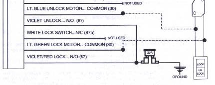
My Prelude uses a 3-wire negative door lock setup... Here is the diagram in my install manual for my alarm... The diagram says I only need to tap into 2 wires... The Unlock motor and the Lock motor...

97 Prelude,  Autopage - Page 2 -- posted image.

The following wiring info talks about 4 different wires for the Prelude...

Power Lock BLACK/ white   -  
Notes: located in the passengers kick at the multiplex control unit in a blue 14 pin connector. May also be in a gray 2 pin connector taped to another harness with blue tape above the driver kick panel.
Power Unlock blue/orange   -  
Notes: located in the passengers kick at the multiplex control unit in a blue 14 pin connector. May also be in a gray 2 pin connector taped to another harness with blue tape above the driver kick panel.
Lock Motor WHITE/ red    bottom of fuse box
Unlock Motor lt.GREEN/ red    bottom of fuse box


Do I just ignore the other the first 2 wires and tap into the "lock motor" and "unlock motor" in my fuse box?


Just want to make sure before I fry something... ;)


Thanks

JiggaFan 
Copper - Posts: 71
Copper spacespace
Joined: February 20, 2003
Location: United States
Posted: May 16, 2005 at 11:45 PM / IP Logged  

in my '97 Accord, that gray 2-wire harness in the driver's kick was very easy to find, and it was indeed wrapped with one layer of blue tape.

as for the alarm, you need to connect those two wires as specified to ground (these are the power input wires for the on board relays, on positive pulse systems, you feed those 2 wires to a +12V source).

connect the other two wires of the alarms to the 2 wires in the gray 2-pin harness and your set!

cleanlude 
Member - Posts: 19
Member spacespace
Joined: May 09, 2005
Posted: May 17, 2005 at 3:55 PM / IP Logged  

I have another question....

The supposed "door trigger" wire, which I believe I have found in a connector beneath the fuse box in the driver's kick...

Well... I disconnected the connector and when I open the driver door with the key in the ignition, it still beeps... and the door ajar light in the dash comes on... Shouldn't that not happen when the connector is disconnected if that is the right wire?

Thanks

cleanlude 
Member - Posts: 19
Member spacespace
Joined: May 09, 2005
Posted: May 17, 2005 at 5:02 PM / IP Logged  

And yet another question...

Can I tap into the parking light wire right behind the dimmer switch? There are a few wires coming out of the dimmer... only one is RED / black, which is the one I need... Can i use this one?

JiggaFan 
Copper - Posts: 71
Copper spacespace
Joined: February 20, 2003
Location: United States
Posted: May 17, 2005 at 5:16 PM / IP Logged  
yeah, gotta use a meter for the wires in question.
stick the red probe in a +12v source (such as the alarm harness), stick the black wire in the wire in question for the door trigger. it should be 0 w/doors closed, 12.xx volts with any/all doors opened.
for the park light wire in question, stick the black probe in a ground source (such as the black wire on the alarm harness or nearest chassis) and poke the red probe through the wire in question (careful not to touch metal with the probe once punched through the wire). turn on the park lights using the switch and your meter should go from 0 to 12.xx volts.
cleanlude 
Member - Posts: 19
Member spacespace
Joined: May 09, 2005
Posted: May 17, 2005 at 5:45 PM / IP Logged  

Park lights are positive and trigger is negative...

Do I need to change settings on DMM between each... I have never used one before... Do I just set it to DC voltage and that's it?

Page of 3

  Printable version Printable version Post ReplyPost New Topic
You cannot post new topics in this forum
You cannot reply to topics in this forum
You cannot delete your posts in this forum
You cannot edit your posts in this forum
You cannot create polls in this forum
You cannot vote in polls in this forum

  •  
Search the12volt.com
Follow the12volt.com Follow the12volt.com on Facebook
Saturday, May 11, 2024 • Copyright © 1999-2024 the12volt.com, All Rights Reserved Privacy Policy & Use of Cookies
Disclaimer: *All information on this site ( the12volt.com ) is provided "as is" without any warranty of any kind, either expressed or implied, including but not limited to fitness for a particular use. Any user assumes the entire risk as to the accuracy and use of this information. Please verify all wire colors and diagrams before applying any information.

Secured by Sectigo
the12volt.com spacer
Support the12volt.com
Top
the12volt.com spacer