


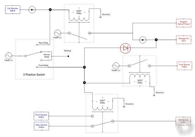
need advice/comments on circuit
Home /
the12volt's Install Bay /
Car Security and Convenience / need advice/comments on circuit ( Topic Closed)


Posted: December 09, 2009 at 8:07 PM / IP Logged


Posted: December 09, 2009 at 8:26 PM / IP Logged
Posted: December 09, 2009 at 9:50 PM / IP Logged
Posted: December 09, 2009 at 10:30 PM / IP Logged
Posted: December 09, 2009 at 10:37 PM / IP Logged

Posted: December 09, 2009 at 10:55 PM / IP Logged
Posted: December 09, 2009 at 11:52 PM / IP Logged
Posted: December 10, 2009 at 12:34 AM / IP Logged

 Hmmm - not too sure what to put....
Jack of all, Master of many?
I had my education interrupted by a 4 year injuneerink degree. (Started as electronics but got cheesed off & I majored in electrical.)
I had an interest in electronics etc and - because I didn't know any better - I often did the impossible. (Unfortunately that habit continued even after my degree.)
I've been involved in various fields & industries including automotive, military, legal, social - but now tend to be somewhat anti-social.
My last employment ended several years ago - a telecomms company - varied jobs from security, OH&S, systems management, power, product exits.
Since then I've probably spent most time trying to bring automotive & political) hobbyists into the new millennium.
Hmmm - not too sure what to put....
Jack of all, Master of many?
I had my education interrupted by a 4 year injuneerink degree. (Started as electronics but got cheesed off & I majored in electrical.)
I had an interest in electronics etc and - because I didn't know any better - I often did the impossible. (Unfortunately that habit continued even after my degree.)
I've been involved in various fields & industries including automotive, military, legal, social - but now tend to be somewhat anti-social.
My last employment ended several years ago - a telecomms company - varied jobs from security, OH&S, systems management, power, product exits.
Since then I've probably spent most time trying to bring automotive & political) hobbyists into the new millennium.Posted: December 10, 2009 at 2:59 PM / IP Logged

Posted: December 10, 2009 at 3:42 PM / IP Logged
 Printable version
| You cannot post new topics in this forum You cannot reply to topics in this forum You cannot delete your posts in this forum You cannot edit your posts in this forum You cannot create polls in this forum You cannot vote in polls in this forum |

| Search the12volt.com |
Follow the12volt.com 
Friday, April 26, 2024 • Copyright © 1999-2024 the12volt.com, All Rights Reserved • Privacy Policy & Use of Cookies

Friday, April 26, 2024 • Copyright © 1999-2024 the12volt.com, All Rights Reserved • Privacy Policy & Use of Cookies
Disclaimer:
*All information on this site ( the12volt.com ) is provided "as is" without any warranty of any kind, either expressed or implied, including but not limited to fitness for a particular use. Any user assumes the entire risk as to the accuracy and use of this information. Please
verify all wire colors and diagrams before applying any information.
