the12volt.com spacer
icon

Progressive Door Unlock 791XV 03 Ram


Post ReplyPost New Topic
< Prev Topic Next Topic >
richy007 
Member - Posts: 11
Member spacespace
Joined: February 22, 2006
Location: United States
Posted: March 16, 2006 at 6:36 PM / IP Logged  

I been reading the posts relating to this feature, but none of them refer to a 2003 Dodge Ram.

My question is, since the same wire is used in the truck to unlock and lock all four doors; how do I connect the progressive door unlock feature from a DEI Viper 791xv to the truck's wiring? The truck came with OEM Keyless entry system.

I know that I have to program the remote to work when I press the unlock/disarm button, within 20 seconds from unlocking the driver door, but I don't know how to connect the wires from the alarm to the the truck's wiring?

Can anybody tell me how to do this?

Thank you

Twelvoltz 
Platinum - Posts: 2,384
Platinum spaceThis member has made a donation to the12volt.com. Click here for more info.spaceThis member consistently provides reliable informationspace
Joined: March 24, 2005
Location: New Jersey, United States
Posted: March 16, 2006 at 6:47 PM / IP Logged  
To accomplish a 2 step unlock on this truck, you would have to use a 5 wire system to the driver's door actuator's unlock wire (blue driver's kick) using the blue - unlock wire from the Viper brain to trigger the relay. Then use the H2 light blue to trigger a relay to send 330ohm - to the oem unlock wire (WHITE/ green).
Hope this helps
richy007 
Member - Posts: 11
Member spacespace
Joined: February 22, 2006
Location: United States
Posted: March 16, 2006 at 6:59 PM / IP Logged  

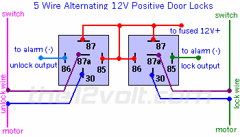
You mean like this?

5 Wire Alternating 12 Volts Positive Door Locks
Like the configuration above, the switch, when moved in either direction, applies both power and ground directly to motor legs  without the use of any relays. Except, at the switch in this case, both motor legs rest at ground . Therefore it is only necessary to change the polarity of one motor leg to lock or unlock the vehicle.
 
Progressive Door Unlock 791XV 03 Ram -- posted image.

Amateurs built the ark. Professionals built the Titanic
Twelvoltz 
Platinum - Posts: 2,384
Platinum spaceThis member has made a donation to the12volt.com. Click here for more info.spaceThis member consistently provides reliable informationspace
Joined: March 24, 2005
Location: New Jersey, United States
Posted: March 16, 2006 at 7:09 PM / IP Logged  
YES, but you only need the unlock side of that diagram.
richy007 
Member - Posts: 11
Member spacespace
Joined: February 22, 2006
Location: United States
Posted: March 16, 2006 at 7:16 PM / IP Logged  

Thank You Twelvoltz.

This set up will unlock the driver door when I press the disarm button once.

The second time i press the button will unlock the remaining doors, do this I connect the wire from output 4 using the original set up.

I got it!!

Thank you.

Amateurs built the ark. Professionals built the Titanic
richy007 
Member - Posts: 11
Member spacespace
Joined: February 22, 2006
Location: United States
Posted: March 20, 2006 at 7:16 PM / IP Logged  

I connected the wires as shown in the diagram, but it does not work.

I get no response from the driver door, it does unlock when I press the disarm button on the remote a second time, but not the first.

I checked all the wires with a multimeter, I do get power coming out of the relay. There are two blue wires in the kickpanel that go into the door. One is for the power mirror and the other one I imagine is for the motor. 

Do I have to use any resistors or diodes for this install?

Can you tell me what am I doing wrong? Progressive Door Unlock 791XV 03 Ram -- posted image.

Amateurs built the ark. Professionals built the Titanic
Ravendarat 
Platinum - Posts: 2,806
Platinum spacespace
Joined: February 23, 2004
Location: Canada
Posted: March 20, 2006 at 7:22 PM / IP Logged  
Switch is in the door, I dont know if you can catch the motor wire in the kick, you might have to go into the door for it. To test this wire, test for voltage change when you rock the switch, then when it tests cut the wire in half. One side should give you voltage when you press unlock, the other wire shouldnt do jack. Thats your wire.
double-secret reverse-osmosis speaker-cone-induced high-level interference distortion, Its a killer
Twelvoltz 
Platinum - Posts: 2,384
Platinum spaceThis member has made a donation to the12volt.com. Click here for more info.spaceThis member consistently provides reliable informationspace
Joined: March 24, 2005
Location: New Jersey, United States
Posted: March 20, 2006 at 7:32 PM / IP Logged  
Raven, I cannot say for 100% the actuator motor is in the kick, but it lists it as so on the DEI tech site.
OK, try this. Try to trigger the relays manually to verify you are on the correct wires. Just take a jumper from ground and tap it to the connection on the relay that comes from the brain of the aftermarket system. One relay should only unlock the driver's door and the other should unlock them both. When you cut the unlock wire for the driver's door did you verify it had 12V when unlocking and that the driver's door did not operate when you cut it? You do not need any additional resistors, the 330ohm you have connected to the 'all doors' connection should do it for the unlock portion.
richy007 
Member - Posts: 11
Member spacespace
Joined: February 22, 2006
Location: United States
Posted: March 20, 2006 at 7:33 PM / IP Logged  

Ravendarat;

So I connected to the blue wire that comes from the switch or the blue wire that goes into the motor/door trigger harnnes?

Do I worry about a ground wire?

Is the input from the relay enough to run the motor?

Amateurs built the ark. Professionals built the Titanic
richy007 
Member - Posts: 11
Member spacespace
Joined: February 22, 2006
Location: United States
Posted: March 20, 2006 at 7:39 PM / IP Logged  

Ok.

Let me try both of these solutions.

Amateurs built the ark. Professionals built the Titanic
Page of 2

  Printable version Printable version Post ReplyPost New Topic
You cannot post new topics in this forum
You cannot reply to topics in this forum
You cannot delete your posts in this forum
You cannot edit your posts in this forum
You cannot create polls in this forum
You cannot vote in polls in this forum

  •  
Search the12volt.com
Follow the12volt.com Follow the12volt.com on Facebook
Friday, May 17, 2024 • Copyright © 1999-2024 the12volt.com, All Rights Reserved Privacy Policy & Use of Cookies
Disclaimer: *All information on this site ( the12volt.com ) is provided "as is" without any warranty of any kind, either expressed or implied, including but not limited to fitness for a particular use. Any user assumes the entire risk as to the accuracy and use of this information. Please verify all wire colors and diagrams before applying any information.

Secured by Sectigo
the12volt.com spacer
Support the12volt.com
Top
the12volt.com spacer