the12volt.com spacer
icon

thermo fan manual switch


Post ReplyPost New Topic
< Prev Topic Next Topic >
aussieman 
Member - Posts: 4
Member spacespace
Joined: November 20, 2009
Location: Australia
Posted: November 20, 2009 at 4:02 PM / IP Logged  
Hi all, I am hoping that someone can help me, I want to set up a switch so I can turn on the radiator fan when I want to, not when the computor wants to.
I have two speed fan, I was hoping I could tap into the low fan relay, the switch I have bought has a light in it to remind me the switch is activated, I would like to set it up so when I turn off the ignition this manual switch is deactivated as well, don't want any flat batteries, of course.
As my user name sugests , i am an aussie so I didn't include my vehilce type as you guys might not be familar with it, [1996 holden commodore] but hoping this won't be a problem with the wiring.
I would really appreciate any advise, thankyou.
i am an idiot 
Platinum - Posts: 13,667
Platinum spaceThis member consistently provides reliable informationspace
Joined: September 21, 2006
Location: Louisiana, United States
Posted: November 20, 2009 at 5:41 PM / IP Logged  
Does the fan relay have a constant feed to the coil and the thermostat switches the ground? 
aussieman 
Member - Posts: 4
Member spacespace
Joined: November 20, 2009
Location: Australia
Posted: November 20, 2009 at 6:14 PM / IP Logged  
I am sorry but that question is way above my knowledge, I guess this is going to be harder than I expected.
thanks for your reply though.
i am an idiot 
Platinum - Posts: 13,667
Platinum spaceThis member consistently provides reliable informationspace
Joined: September 21, 2006
Location: Louisiana, United States
Posted: November 20, 2009 at 6:25 PM / IP Logged  
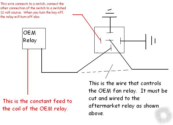
If so and only if that is the case, the following diagram should help you.
thermo fan manual switch -- posted image.
oldspark 
Gold - Posts: 4,913
Gold spacespace
Joined: November 03, 2008
Location: Australia
Posted: November 20, 2009 at 7:01 PM / IP Logged  
If the original relay is switched by grounding it, then you can simply wire a grounding switch in parallel.
(That means the relay solenoid is always hot +12V so the relay is actuated by grounding its other end. The same idea will NOT work on hot-switched system - something will blow!)
Older cars commonly used grounding for their horns - ie, a grounded horn button feeding a 3 terminal "hot" relay (or hot 4 terminal relay with +12V connected to contact & solenoid - say #30 & #86).
The core of the computer itself uses ground switching, but that will be buffered before it is presented to its output, and that buffering might change the signal to hot switching (ie, +5V or +12V output).
Ground switching is equivalent to "Open Collector" outputs as recently discussed at 12Volt's what is a 'pull up resistor'.
i am an idiot 
Platinum - Posts: 13,667
Platinum spaceThis member consistently provides reliable informationspace
Joined: September 21, 2006
Location: Louisiana, United States
Posted: November 20, 2009 at 7:13 PM / IP Logged  
He mentioned that the relay was controlled by the computer of the vehicle.  Grounding the wire without isolating it from the computer could cause problems.   
oldspark 
Gold - Posts: 4,913
Gold spacespace
Joined: November 03, 2008
Location: Australia
Posted: November 20, 2009 at 7:27 PM / IP Logged  
I must stress "ONLY if the original relay is switched by grounding it".
I shall re-edit to highlight, and add ONLY.
Thanks.
PS - Dang! Wrong rules or wrong forum. I can't back edit.
I really must query management....
Please aussieman, be very aware of the implications.
At least being Aussie you'll understand my accent eh?
aussieman 
Member - Posts: 4
Member spacespace
Joined: November 20, 2009
Location: Australia
Posted: November 21, 2009 at 12:14 AM / IP Logged  
Sorry I took so long to get back to you and thanks very much for your help guys,but I think I have bitten off more than I can chew [ so to speak ], yes I am aware of the implications that is why I didn't want to touch anything before I found out for sure if it would be ok.
I will try to explain as best I can, with an earthed testing light I can get a power out of one of the low fan relays connections, only when ignition is turn on, but nothing from the same connection when ignition is off.
So can I run a wire from that connection of the relay to a switch mounted on the dash somewere and then earth that switch to something close by ?
If it turns out to much for me, I will get a pro to do it, but I like trying to do stuff myself, if possible.
thanks again.
oldspark 
Gold - Posts: 4,913
Gold spacespace
Joined: November 03, 2008
Location: Australia
Posted: November 21, 2009 at 2:15 AM / IP Logged  
Excellent info!   
Alas no - yours is not earth switched.
If it was, 2 terminals would be +12V with ignition ON and fan OFF.
You may be able to parallel a second relay - ie, from +12V to the fan (and turned on buy a dash switch) - but that depends on the wiring - it could be damaging.
So it looks like you need to get a pro. (Rats!)
aussieman 
Member - Posts: 4
Member spacespace
Joined: November 20, 2009
Location: Australia
Posted: November 27, 2009 at 1:51 PM / IP Logged  
Solved, second relay was earth.
thanks for your help and a special thank you to oldspark.

Sorry, you can NOT post a reply.
This topic is closed.

  Printable version Printable version Post ReplyPost New Topic
You cannot post new topics in this forum
You cannot reply to topics in this forum
You cannot delete your posts in this forum
You cannot edit your posts in this forum
You cannot create polls in this forum
You cannot vote in polls in this forum

  •  
Search the12volt.com
Follow the12volt.com Follow the12volt.com on Facebook
Sunday, April 28, 2024 • Copyright © 1999-2024 the12volt.com, All Rights Reserved Privacy Policy & Use of Cookies
Disclaimer: *All information on this site ( the12volt.com ) is provided "as is" without any warranty of any kind, either expressed or implied, including but not limited to fitness for a particular use. Any user assumes the entire risk as to the accuracy and use of this information. Please verify all wire colors and diagrams before applying any information.

Secured by Sectigo
the12volt.com spacer
Support the12volt.com
Top
the12volt.com spacer