the12volt.com spacer
icon

2004 tundra double cab wiring pin/plug?


Post ReplyPost New Topic
< Prev Topic Next Topic >
bpowa 
Member - Posts: 29
Member spacespace
Joined: January 17, 2013
Location: United States
Posted: February 05, 2013 at 6:21 PM / IP Logged  
Well I cannot find anything on this truck searching the net. As if no one ever really did a DIY..
Sound like everyone is using a bypass.   I would have went with one if I knew ahead of time.
I dont want to install a bypass when I only have one issue I have to complete..
Larry
soundnsecurity 
Gold - Posts: 2,716
Gold spaceThis member has made a donation to the12volt.com. Click here for more info.spacespace
Joined: November 10, 2008
Location: Louisiana, United States
Posted: February 05, 2013 at 7:08 PM / IP Logged  
can you take some pictures of how you wired the locks at the switch? it would help me figure it out for you. do the locks work like normal with the switch.
howie ll 
Pot Metal - Posts: 16,466
Pot Metal spacespace
Joined: January 09, 2007
Location: United Kingdom
Posted: February 06, 2013 at 1:09 AM / IP Logged  
Disconnect the lock and unlock leads from your R/S. Take your DMM,set it to 20VDC, place the red probe on a constant source and place the black probe on the lock and unlock wires in sequence then lock and unlock with the remote.
You should get a 12VDC reading each time.
If not the R/S is faulty.
If you do, then the R/S is OK, so repeat this test at the joins in the door.
If not your wiring is faulty, bad join, open circuit etc.
If OK then ground each join in turn.
If that locks and unlocks the vehicle, look again at how you did the relay, diode position, etc.
I'm assuming soldered joints or all bets are off.
bpowa 
Member - Posts: 29
Member spacespace
Joined: January 17, 2013
Location: United States
Posted: February 06, 2013 at 1:28 PM / IP Logged  
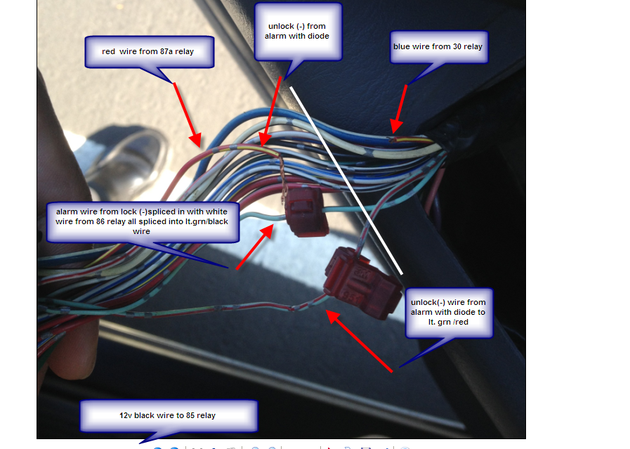
here is a picture from door panel control..
please let me know if I have it correct.. I will try to find time to test the wires..
Larry
bpowa 
Member - Posts: 29
Member spacespace
Joined: January 17, 2013
Location: United States
Posted: February 06, 2013 at 1:46 PM / IP Logged  
sorry.. I cant post pic..
here is a link
2004 tundra double cab wiring pin/plug? - Page 5 -- posted image.
Larry
soundnsecurity 
Gold - Posts: 2,716
Gold spaceThis member has made a donation to the12volt.com. Click here for more info.spacespace
Joined: November 10, 2008
Location: Louisiana, United States
Posted: February 06, 2013 at 2:02 PM / IP Logged  
your negative unlock that goes to the RED / yellow wire needs to go the the other side of the wire when it gets split with the relay. other than that the only other problem i see is that you are using T-taps for your connections, this could cause a connection problem because they dont contact the wire tight enough sometimes. and make sure your diodes are facing the right way, the stripe needs to go towards the alarm.
bpowa 
Member - Posts: 29
Member spacespace
Joined: January 17, 2013
Location: United States
Posted: February 06, 2013 at 2:45 PM / IP Logged  
Well from my picture above the controller is to the left side, and the motor is to the right.. Its the opposite to the diagram.. Can you confirm?
Those t taps were there prior. But I use them to tap in temporary.
I will make solid connections when all the wiring is correct and tuck neatly.
Larry
howie ll 
Pot Metal - Posts: 16,466
Pot Metal spacespace
Joined: January 09, 2007
Location: United Kingdom
Posted: February 06, 2013 at 4:54 PM / IP Logged  
And you will get constantly recurring problems with those T-taps.
Loose them and solder now.
soundnsecurity 
Gold - Posts: 2,716
Gold spaceThis member has made a donation to the12volt.com. Click here for more info.spacespace
Joined: November 10, 2008
Location: Louisiana, United States
Posted: February 06, 2013 at 4:58 PM / IP Logged  
no, if you look at the diagram carefully it has the motor AND switch on the same side. it says motor on top and switch on the bottom. the part that says motor is a separate part of the diagram
bpowa 
Member - Posts: 29
Member spacespace
Joined: January 17, 2013
Location: United States
Posted: February 06, 2013 at 5:28 PM / IP Logged  
Yes.. I will try that out.. Diagram is better than the other 1070 I saw. But For the armature installer like myself its hard to determine.
Thanks I will try that out.. Hopefully in the next couple days..
Larry
Page of 6

  Printable version Printable version Post ReplyPost New Topic
You cannot post new topics in this forum
You cannot reply to topics in this forum
You cannot delete your posts in this forum
You cannot edit your posts in this forum
You cannot create polls in this forum
You cannot vote in polls in this forum

  •  
Search the12volt.com
Follow the12volt.com Follow the12volt.com on Facebook
Saturday, August 30, 2025 • Copyright © 1999-2025 the12volt.com, All Rights Reserved Privacy Policy & Use of Cookies
Disclaimer: *All information on this site ( the12volt.com ) is provided "as is" without any warranty of any kind, either expressed or implied, including but not limited to fitness for a particular use. Any user assumes the entire risk as to the accuracy and use of this information. Please verify all wire colors and diagrams before applying any information.

Secured by Sectigo
the12volt.com spacer
Support the12volt.com
Top
the12volt.com spacer