the12volt.com spacer
icon

93 Z71 Door Locks


Post ReplyPost New Topic
< Prev Topic Next Topic >
Fulblown 
Member - Posts: 3
Member spacespace
Joined: December 08, 2003
Location: Canada
Posted: December 08, 2003 at 4:25 PM / IP Logged  

Hey guys (and girls) I am new to the forum.  First I would to say this is an AWESOME forum and website. Kudos to everyone involved!!OK I have been browsing the site looking for info on how to get some power door locks working.The Truck is a 1993 Chev truck (Z71) and I am installing a Black Widow 7150 FM Alarm/starter combo.I have tryed connecting the relays in the reverse polarity config. and the 5 Wire Alternating config. neither work.I am using the BLUE wire for locking and the BLACK/ red wire for unlock....it just will not work.  I know that the switched still work because I have tested and re-tested them after each unsuccessful attempt.

PLEASE....any suggestions would be greatly appreiciated.

Fulblown MotorSports
Joshua
HamiltonAudio 
Silver - Posts: 278
Silver spacespace
Joined: October 15, 2003
Posted: December 08, 2003 at 8:57 PM / IP Logged  

did you test to ensure you you grabbed the right lock/unlock wires?  baby blue and black sound right for that truck...each wire will test +12V when hitting the switch up and down...this way you know for sure you've got the right wires (there are often multiples of the same colour)

It is the 5 wire, reversal rest at ground circuit that you need.  You'll need to cut the lock/unlock wires when you find them, and end up with a switch side and vehicle side.  Test each "side" of each wire while hitting the doorlock switch....the side that still shows +12V when switching is the "switch side".

Simply follow the diagram on here for 5 wire reversal rest at ground circuit.  Ensure your starter is providing a negative pulse (most diagrams are designed for that).  You'll notice that when the d/l wires are cut, the switch will stop functioning (duh!).  However, when the relays are wired correctly, the switch will work again...its a good hint things are right...

Perhaps the outputs off the unit aren't working right?  did you try manually grounding the lock/unlock wires of the relay harness to see?

b

Velocity Motors 
Moderator - Posts: 12,488
Moderator spaceThis member has made a donation to the12volt.com. Click here for more info.spaceThis member has been recognized as an authority in Electrical Theory. Click here for more info.spaceThis member has been recognized as an authority in Fabrication. Click here for more info.spaceThis member has been recognized as an authority in Mobile Audio and Video. Click here for more info.spaceThis member has been recognized as an authority in Mobile Security and Convenience. Click here for more info.spacespace
Joined: March 08, 2002
Location: Manitoba, Canada
Posted: December 09, 2003 at 9:15 AM / IP Logged  
Hey Josh, is the truck a 4 door or had OEM keyless ??
Jeff
Velocity Custom Home Theater
Mobile Audio/Video Specialist
Morden, Manitoba CANADA
Fulblown 
Member - Posts: 3
Member spacespace
Joined: December 08, 2003
Location: Canada
Posted: December 10, 2003 at 2:18 PM / IP Logged  

The truck is a 2 door, no keyless.  Just the regular power locks. You hit the switch once and it either locks or unlocks both doors. Were in the site is the 5 WIRE Revere rest at GROUND DIAGRAM. I know were the 5 wire alternating and the reverse polarity circuit is, but I cannot find that one.

Thank you

Fulblown MotorSports
Joshua
HamiltonAudio 
Silver - Posts: 278
Silver spacespace
Joined: October 15, 2003
Posted: December 10, 2003 at 2:36 PM / IP Logged  

there are usually more than one name for a circuit.  The one you want is where you find the lock and unlock wires that show a positive pulse when tested.  Then CUT the lock and unlock wires, giving you 4 "sides".  You'll have a pair of "switch side" wires and pair of "motor" or "vehicle" side wires.  From there, using the right dual relay socket is easy stuff...

b

HamiltonAudio 
Silver - Posts: 278
Silver spacespace
Joined: October 15, 2003
Posted: December 10, 2003 at 2:39 PM / IP Logged  
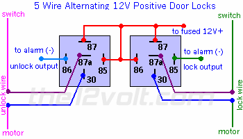
93 Z71 Door Locks -- posted image. 5 Wire Alternating 12 Volts Positive Door Locks
Like the configuration above, the switch, when moved in either direction, applies both power and ground directly to motor legs  without the use of any relays. Except, at the switch in this case, both motor legs rest at ground . Therefore it is only necessary to change the polarity of one motor leg to lock or unlock the vehicle.
 
93 Z71 Door Locks -- posted image.
Fulblown 
Member - Posts: 3
Member spacespace
Joined: December 08, 2003
Location: Canada
Posted: December 10, 2003 at 11:42 PM / IP Logged  

Hey guys thanks for your help, but I am still having problems!!

87a on my relay is a constant power source if I have 87 supplied with 12V. Is this right??

IS THIS RIGHT???

Fulblown MotorSports
Joshua
Steveo_supremo 
Member - Posts: 34
Member spacespace
Joined: September 23, 2003
Location: Canada
Posted: December 11, 2003 at 9:40 AM / IP Logged  
No that is not right. I had the same problem on my 94 chev pick-up. I bought the relays at Canadian Tire, and they said 87 and 87a on them, but really it was just two 87's. Get the proper relays and i bet it works like a charm.
defective 
Silver - Posts: 642
Silver spacespace
Joined: August 20, 2003
Location: Canada
Posted: December 11, 2003 at 3:09 PM / IP Logged  
damn bosch's....grin

Sorry, you can NOT post a reply.
This topic is closed.

  Printable version Printable version Post ReplyPost New Topic
You cannot post new topics in this forum
You cannot reply to topics in this forum
You cannot delete your posts in this forum
You cannot edit your posts in this forum
You cannot create polls in this forum
You cannot vote in polls in this forum

  •  
Search the12volt.com
Follow the12volt.com Follow the12volt.com on Facebook
Thursday, October 31, 2024 • Copyright © 1999-2024 the12volt.com, All Rights Reserved Privacy Policy & Use of Cookies
Disclaimer: *All information on this site ( the12volt.com ) is provided "as is" without any warranty of any kind, either expressed or implied, including but not limited to fitness for a particular use. Any user assumes the entire risk as to the accuracy and use of this information. Please verify all wire colors and diagrams before applying any information.

Secured by Sectigo
the12volt.com spacer
Support the12volt.com
Top
the12volt.com spacer