Posted: June 01, 2008 at 10:33 AM / IP Logged
Posted: June 02, 2008 at 7:09 PM / IP Logged
Posted: June 02, 2008 at 10:33 PM / IP Logged
Posted: June 04, 2008 at 1:44 AM / IP Logged
Sorry, you can NOT post a reply.
This topic is closed.
 Printable version


| You cannot post new topics in this forum You cannot reply to topics in this forum You cannot delete your posts in this forum You cannot edit your posts in this forum You cannot create polls in this forum You cannot vote in polls in this forum |

| Search the12volt.com |
Follow the12volt.com 
Wednesday, October 29, 2025 • Copyright © 1999-2025 the12volt.com, All Rights Reserved • Privacy Policy & Use of Cookies


Wednesday, October 29, 2025 • Copyright © 1999-2025 the12volt.com, All Rights Reserved • Privacy Policy & Use of Cookies
Disclaimer:
*All information on this site ( the12volt.com ) is provided "as is" without any warranty of any kind, either expressed or implied, including but not limited to fitness for a particular use. Any user assumes the entire risk as to the accuracy and use of this information. Please
verify all wire colors and diagrams before applying any information.


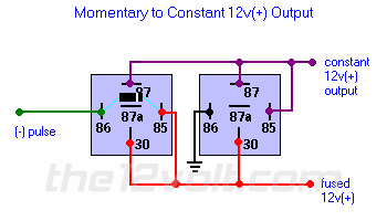
 The relay on the left energizes only when the pulse is coming in, and when it does, it connects the 12V input from the bottom (terminal 30) to the top (terminal 87).
The 12V goes to the coil of the relay on the right, and now it energizes, and also connects the 12V from the bottom to the top.
Because there's a connection between the terminal 87 and coil input terminal 85, it supplies its own 12V power to the coil and holds itself energized, even if the first relay opens up again. The first relay won't stay on if the pulse is removed, it's only the second relay that stays on, until the fused 12V source on the bottom is removed.
The diode on the left relay is only needed if the thing supplying the (-) pulse is sensitive to the high voltage spike that the relay coil puts out when turning off. Usually needed to protect electronic or solid state drivers, and not necessary if a simple mechanical switch is being used.