


2006 Nissan Sentra Remote Start Pictorial
Home /
the12volt's Install Bay /
Car Security and Convenience - Alarm/Remote Start Pictorials / 2006 Nissan Sentra Remote Start Pictorial ( Topic Closed)


Posted: January 05, 2012 at 8:15 PM / IP Logged
 - Remove 2 10mm bolts from small metal support bracket. Lift up and out to remove. (No Picture)
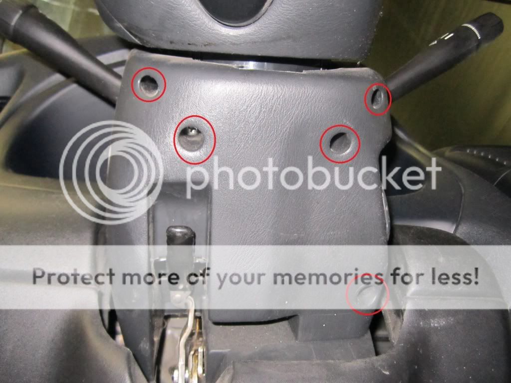
- Remove 5 phillips head screws from lower steering column panel. Pull down to remove.
- Remove 2 10mm bolts from small metal support bracket. Lift up and out to remove. (No Picture)
- Remove 5 phillips head screws from lower steering column panel. Pull down to remove.
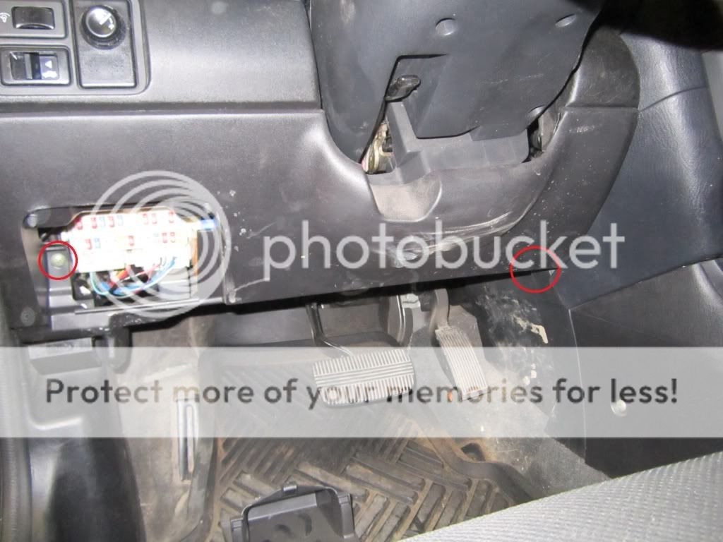
 - Remove door sill plastic. Remove plastic clip holding back of kick panel. Pull rubber weatherstripping back to free kick panel. Pull kick panel towards center of vehicle to remove.
Installation:
- Ignition wires found at ignition switch. Unplug switch and route to right side of steering wheel for more slack or connect further down harness depending on location of main unit and length of wires.
- Remove door sill plastic. Remove plastic clip holding back of kick panel. Pull rubber weatherstripping back to free kick panel. Pull kick panel towards center of vehicle to remove.
Installation:
- Ignition wires found at ignition switch. Unplug switch and route to right side of steering wheel for more slack or connect further down harness depending on location of main unit and length of wires.
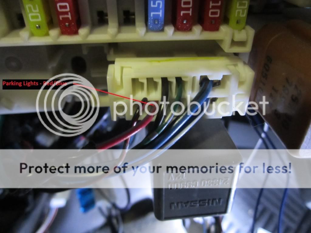
 - Parking lights (+) found in plug on lower right of fuse box.
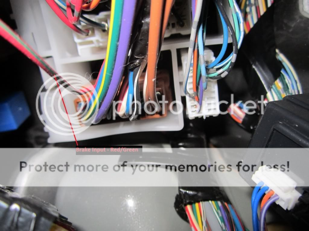
 - Brake wire input found in brown plug above driver kick panel (behind fusebox).
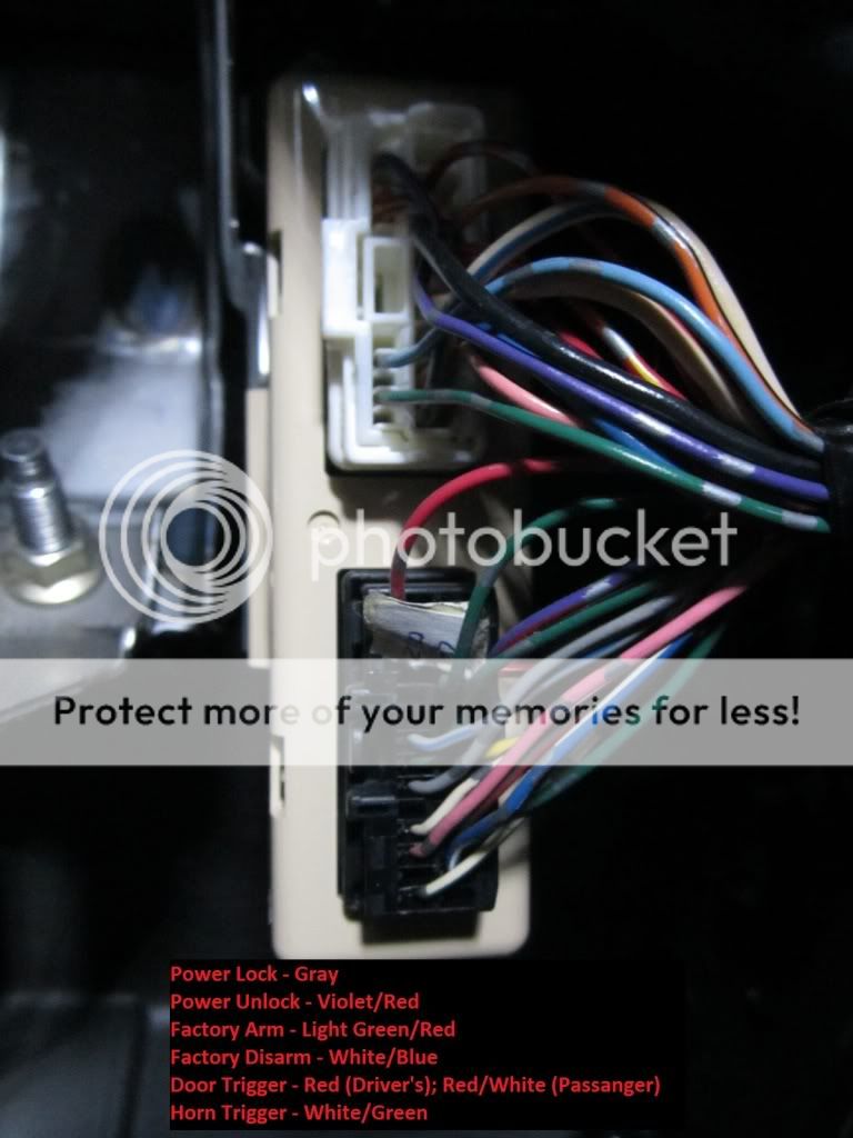
 - Multiple wires found at SECU to the right of the steering column.
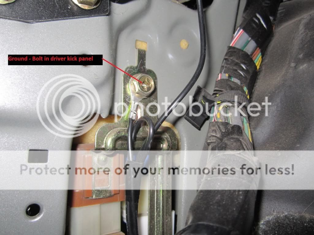
 - Ground to factory bolt in driver kick panel. Scrape paint behind metal bracket to ensure good ground.
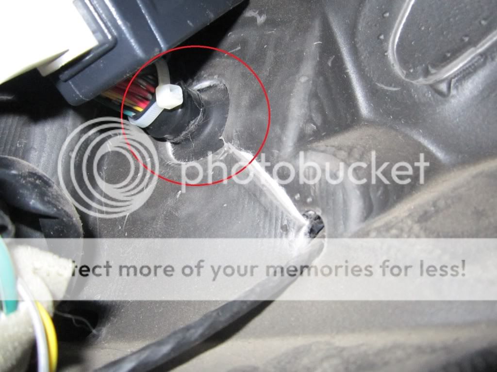
 - Access to engine bay through harness boot above driver kick panel.
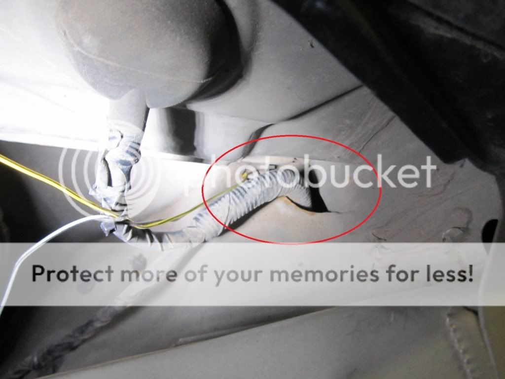
 - Wire boot will lead behind inner wheel well and MAY be able to be fished through into the engine bay. Some clips may need to be removed in inner wheel well to reach behind and route through opening and into engine bay. Attach to current wire harness to prevent scraping against metal with vibrations.
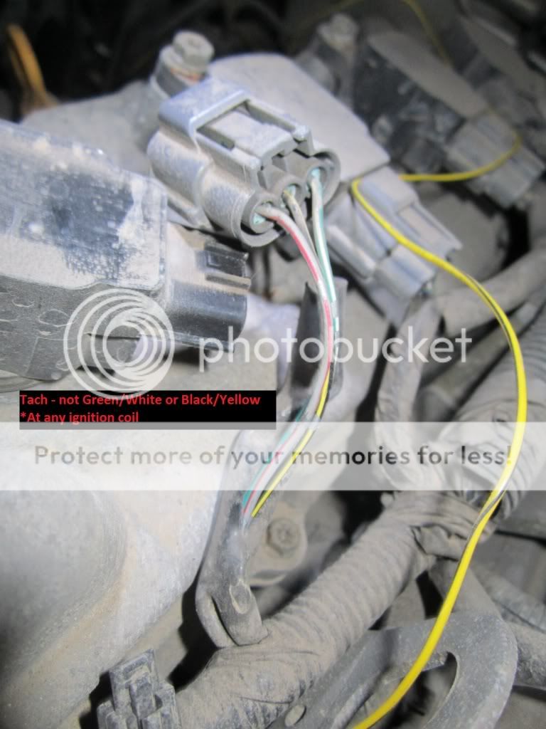
 - Tach signal found at any ignition coil.
 - Hood pin required aftermarket pin to be added.

Posted: March 01, 2012 at 11:42 AM / IP Logged
Posted: March 02, 2012 at 5:19 AM / IP Logged

Posted: March 03, 2012 at 2:29 AM / IP Logged
Sorry, you can NOT post a reply.
This topic is closed.
 Printable version
| You cannot post new topics in this forum You cannot reply to topics in this forum You cannot delete your posts in this forum You cannot edit your posts in this forum You cannot create polls in this forum You cannot vote in polls in this forum |

| Search the12volt.com |
Follow the12volt.com 
Saturday, May 23, 2026 • Copyright © 1999-2026 the12volt.com, All Rights Reserved • Privacy Policy & Use of Cookies

Saturday, May 23, 2026 • Copyright © 1999-2026 the12volt.com, All Rights Reserved • Privacy Policy & Use of Cookies
Disclaimer:
*All information on this site ( the12volt.com ) is provided "as is" without any warranty of any kind, either expressed or implied, including but not limited to fitness for a particular use. Any user assumes the entire risk as to the accuracy and use of this information. Please
verify all wire colors and diagrams before applying any information.
