the12volt.com spacer
icon

04 4runner remote start w/factory remote


Post ReplyPost New Topic
< Prev Topic Next Topic >
pjbrownva 
Member - Posts: 11
Member spacespace
Joined: March 08, 2012
Location: Virginia, United States
Posted: December 19, 2016 at 5:11 PM / IP Logged Link to Post Post Reply Quote pjbrownva
mav2287 wrote:
Did you ever get to try this? Did it work?
I didn't try it. I wasn't sure what the grey box in the wiring diagram meant, and it didn't look (to me) like cutting the red (or maybe red w/ black... can't quite tell from my photo posted) wire on the far left would do any good, because inside the grey box in the diagram, the body ECU wire is also connected to the fused + input right next to it.
Without more information, I didn't want to risk messing something up, or cutting a wire that (if for instance) my solder connection was unreliable, could possibly cause my car to turn off while driving down the highway.
The risk-reward didn't pay off in my mind.   There were too many unknowns and, while I don't mind cutting and soldering factor wires, it seemed to me that this connection could possibly be a very critical one.   Also... since I didn't have more info, I didn't want to risk the possibility of maybe damaging the body ECU while I played around with and experimented on the unknown.... not worth it.
If you try it and it works, or you find an answer, by all means share. I actually got rid of my 2004, and now have a 2008. I haven't even looked to see if it would be the same or different to put one of these units in my new 4Runner.
I can say that it worked very,very well... although (for some reason) on days when it was below zero, the remote key start sometimes didn't work. Despite trouble shooting, and even resoldering all relevant wires, I could determine that the key bypass wasn't doing it's job, but could never find out why or fix it... still, I suspect that this was my fault somehow, and a byproduct of my install.
Since it is RARELY below zero where I live (maybe 2 or 3 times a year during the daytime) I just decided to deal with both issues, and use my key to unlock the truck while it was under remote start.
The other thing to note is that, while the connections and wiring were fairly straight forward, there were A LOT of them... I believe I counted 42 connections in all.
Not doing this for a living, it took me many, many, many hours to completely finish the install... but everything did work!
Good luck if you go this route. I was happy with the result, but in the end I think that I might have been better served to have taken it to a car stereo specialty shop, and let them sell me and install a system. They can do this soooo much faster than it took me. :)
-Phil
pjbrownva 
Member - Posts: 11
Member spacespace
Joined: March 08, 2012
Location: Virginia, United States
Posted: December 20, 2016 at 11:24 AM / IP Logged Link to Post Post Reply Quote pjbrownva
So your post piqued my interest.
As I said, I sold my '04, and now have an '08 without the remote start... nonetheless, I have revisited the diagrams, and I think it can be done.
The "Grey box" appears to be "Junction block and wire harness connector"
04 4runner remote start w/factory remote - Page 2 - Last Post -- posted image.
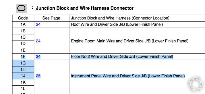
To me that means that it is probably a special "pig tail" type connector that plugs into a junction block, has it's own internal connections within it and then has a plug to plug into a wire harness.
04 4runner remote start w/factory remote - Page 2 - Last Post -- posted image.
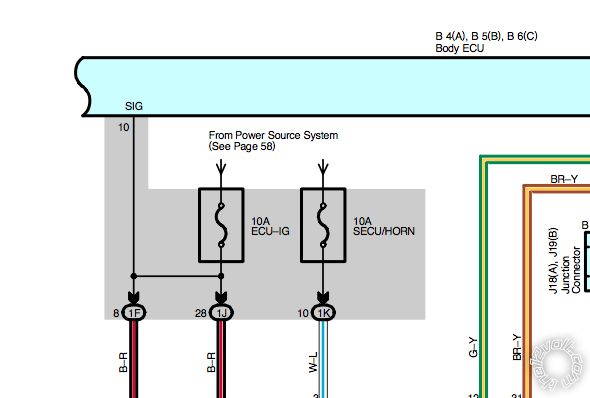
Based on that information you will want to focus on the connector at the left driver's side kick panel, and find the connector into the "Body ECU" that includes pin numbers 10 on the Body ECU (the "SIG" stands for Secondary Ignition" -- i think). The wire should be in a pigtail or wiring harness and inside that harness Body ECU pin 10 should be connected to Pin 8 on connector "1F" which according to the image above connects the "Floor no 2 wire and driver side Junction box (Lower Finish Panel)".    Inside that pigtail harness, the same pin should also be connected to pin 28 on 1J which is the "Instrument panel and driver side junction box (lower finish panel)"
So you will have to examine that connector, and find the right wire to cut.
As indicated in the "Service Hints" (below)
04 4runner remote start w/factory remote - Page 2 - Last Post -- posted image.
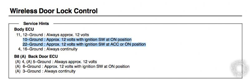
On the ECU, both Pin 10 and Pin 22 are at +12V when the ignition switch is "ON".
Inside the harness, cut the wire where it leads into pin 10, then test to see if you can unlock the doors when the engine is running via remote start.
If cutting the wire inside the harness that connects to pin 10 still doesn't give the desired response, you may need to cut the wire that leads to body ECU pin 22 as well -- since this wire is +12V for the ignition switch in both "ACC" and "ON" position.
Both of those pins are at +12V (in reference to ground) when the ignition switch is "on".   
If it does work, then you will need to have that wire (or wires) disconnected when the remote start is running, and connected at all other times.
Do this by adding one relay for each wire that needs to be cut, and connect them so that the wire is normally connected when the relay is not powered, and when the remote start has the engine running, the relay is powered causing the the wire(s) to be disconnected.
When remote start isn't running, the relay (or relays) will close again, reconnecting those wires.
04 4runner remote start w/factory remote - Page 2 - Last Post -- posted image.
If you go this route, don't forget to put a diode across the correct relay wires to prevent voltage spikes when the relay changes state (search and read for info on this if you are not familiar with what I'm talking about... it's a very standard issue and solution for hooking up relays), Because these relays will be connected to on board computers, you don't want to risk damaging them due to voltage spikes when the relays are triggered.
I feel confident that this should work for you (or anyone else), and will not pose the types of risk that I was concerned about. Of course, you will have to carefully examine and test the pigtail/wiring harness, because the schematics don't tell you how it is wired internally -- and I am assuming that it is in fact WIRES and not -- for instance -- a circuit board, that makes the connections. Whatever it is, if you do it, please post photos in this thread so others (including myself) can see.
Based on this info, I'll have to determine if I want to look for another one of these units and install it (with ALL of those connections) or if I want to have a local shop put in a basic, one-way remote start for me. If go local... I'll definitely do a stereo and alarm speciality shop, and not one of the big box stores such as Best Buy.
I want to make sure that everything is done neatly, professionally and correctly, and there are a lot of subtle points to get it right!
-Phil
pjbrownva 
Member - Posts: 11
Member spacespace
Joined: March 08, 2012
Location: Virginia, United States
Posted: December 20, 2016 at 11:56 AM / IP Logged Link to Post Post Reply Quote pjbrownva
mav2287 wrote:
Did you ever get to try this? Did it work?
pjbrownva wrote:
I have it (remote start) hooked up and working.
As noted in this 7 year old thread:    
4 Runner remote start with factory remote
Someone posted that when the 4Runner is running, the factory key fob features such as lock, unlock and window down are disabled.    
In a much earlier thread Chris Luongo wrote:
Chris Luongo wrote:
Probably, you can look at that module for a wire that tests as ignition, and interrupt it during remote start...
...And if so, you must have triggered the keysense wire, right? That's going to be a problem----even with the ignition off, t
So I finally have found the answer (but haven't tested it).
Chirs is (mostly) right...   
The answer is that there is a Door Lock Control Module, and a "Body ECU". The Body ECU has a "Junction Block Connector and Harness" and inside that harness pin 10 of the Body ECU "SIG" input (Secondary Ignition) is connected to other wires. You need to cut that wire within the harness, and the door lock function SHOULD work when the 4runner is running form remote start.
You will need to add a relay so that the wire is normally connected, and only disconnected when the remote start module has the engine running. Use a diode to protect the Body ECU from voltage spikes when the relay changes state. Do a search if you aren't sure what I'm referring to -- this is a very common issue and solution when dealing with relays.
If I install a similar system in my New 4Runner... I'll post here and let everyone know what I found out when I got to this step. Right now, I got rid of my old 4Runner that had the remote start, and I haven't put anything in my new one yet.
    -Philip
-Phil
pjbrownva 
Member - Posts: 11
Member spacespace
Joined: March 08, 2012
Location: Virginia, United States
Posted: December 20, 2016 at 12:07 PM / IP Logged Link to Post Post Reply Quote pjbrownva
You will also need to wire the system so that the key sense is triggered while you are starting the truck, but NOT triggered once the truck is running.
I haven't looked at how to do this, there might be an output from the remote starter that is only powered while cranking, if so -- that is the answer.
If it gets more complicated than that, you may even need to do some trickery such as adding a "Pac TR7" relay, and connecting and programming it in such a way that it will only power the key-sense for a short period of time when triggered, and then go back to not powering it, or something else creative.
-Phil
Page of 2

If you wish to post a reply to this topic, you must first login.
If you are not already registered, you must first register.

  Printable version Printable version Post ReplyPost New Topic
You cannot post new topics in this forum
You cannot reply to topics in this forum
You cannot delete your posts in this forum
You cannot edit your posts in this forum
You cannot create polls in this forum
You cannot vote in polls in this forum

  •  
Search the12volt.com
Follow the12volt.com Follow the12volt.com on Facebook
Thursday, May 23, 2024 • Copyright © 1999-2024 the12volt.com, All Rights Reserved Privacy Policy & Use of Cookies
Disclaimer: *All information on this site ( the12volt.com ) is provided "as is" without any warranty of any kind, either expressed or implied, including but not limited to fitness for a particular use. Any user assumes the entire risk as to the accuracy and use of this information. Please verify all wire colors and diagrams before applying any information.

Secured by Sectigo
the12volt.com spacer
Support the12volt.com
Top
the12volt.com spacer