the12volt.com spacer
icon

wiring a hobby sign with leds + el wire


Post ReplyPost New Topic
< Prev Topic Next Topic >
fcs22 
Member - Posts: 5
Member spacespace
Joined: December 06, 2013
Posted: December 06, 2013 at 1:15 PM / IP Logged  
hi-
i'm a total newbie to this, so all help is appreciated, and you can't tell me anything too basic.
designing a hobby project -- i am wiring a small sign.
the components are as follows:
58 x 5mm LEDs (12v)
12 x 3mm LEDs (12v)
1 x 2.3 EL wire
1 x 12v inverter to power the EL wire
1 x 12v wireless relay switch (with paired remote)
1 x 12v power supply (8 x AA batteries)
I need help designing this circuit.
from what i can tell reading these forums, my best bet is to split up the LEDs into groups of 4 to divide the 12v to the 3v needed. the EL wire has a power inverter that needs 12v input.
how do i lay it all out? where in the chain should i put the switch?
oldspark 
Gold - Posts: 4,913
Gold spacespace
Joined: November 03, 2008
Location: Australia
Posted: December 06, 2013 at 5:16 PM / IP Logged  
Welcome to the12volt!
And good onya for trying something like this - it's a pretty safe intro that covers a lot of basics - but I'll leave my praise ramble for now.
You said "12V" LEDs, but 12V LEDs involve a resistor and LED or resistor and a string (group) of LEDs.
LEDs are usually ~2V for red & green, ~3.4V for white, ~4.5V for blue, etc.   
And then - yes - wire "strings" or series LEDs where the number of LEDs per string is determined by the SUM of all LED voltages (aka VL) not exceeding the (minimum) supply voltage - eg, 12V. or maybe 11V allowing for a flat battery etc.
A resistor is then used to "drop" the remaining voltage - and also limit the maximum string current.
Typically for white LEDs, a max of 3 per string - ie, 3 x 3.2V or 3 x 3.5V = 9.6V or 10.5V which is comfortably less than 12V.
If red which were traditionally 1.7V but now 2V or 2.1V, assume 2V hence we could have 6 LEDs = 6 x 2V = 12V (especially in 12V vehicles which are usually more like 12.5V to 14.5V), but we might want to include a resistor so hence maybe only 5 (or 4 or 3) for a "12V" supply.
We need to know the LED current to calculate the resistor value (R = V/I from Ohm's Law V = IR), but your LEDs are probably rated as 20mA. (All LEDs in a string will have the same current thru them.)
NOTE - one resistor per string. The (12V) strings are then paralleled together.
Instead of me rambling, look at electronicsclub.info - Light Emitting Diodes (LEDs).
There are other good web references and LED resistor calculators.
Maybe then get back with your preliminary design - how many LEDs with what VL voltages and currents and resistor values and I or others might do a sanity check BEFORE you buy extra components or assemble it etc.
Also note that LEDs are not that critical. Many people wire strings of (say) 6 or 7 reds or 4 whites direct to 12V vehicle systems (ie, 14.4V) without resistors, but resistors should help maintain a more consistent illumination (brightness) with varying voltage as well as help ensure the LED's max current is not exceeded - though less current may not make much practical difference to brightness, and (slight) over-current usually means a shorter life (ie, less than several years) rather than any instant destruction.
As to the EL wire, I presume you mean an ElectroLuminescent display and hence the inverter.
That should simply be a case of wiring the EL to the inverter as per instructions, and the inverter's 12V to the batteries (8 x 1.5V in series = 12V).
The wireless remote I presume is the master on-off switch that sits between the batteries and the rest.
How long the batteries last depends on total current consumption, but that's another issue. However a 12VDC plugpack could be substituted, or even a car battery etc though they are ~12.7V fully charged (and higher when being charged), but the use of LED string resistors should mean that's not a problem. You'd have to check what voltage input the inverter tolerates.   
fcs22 
Member - Posts: 5
Member spacespace
Joined: December 06, 2013
Posted: December 07, 2013 at 3:32 PM / IP Logged  
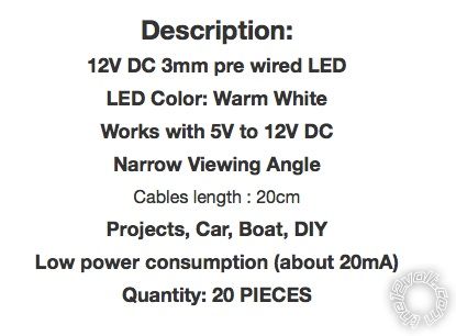
oldspark- thanks for your help. here are the specs of the LEDs i bought on ebay. they list on ebay as 12V...
wiring a hobby sign with leds + el wire - Last Post -- posted image.
does that mean there's already a transistor in them?
ebay link here:
http://www./itm/50-x-Warm-White-5mm-LEDs-Pre-Wired-Light-12V-20cm-Bulbs-/300516795565
oldspark 
Gold - Posts: 4,913
Gold spacespace
Joined: November 03, 2008
Location: Australia
Posted: December 07, 2013 at 5:11 PM / IP Logged  
They are white LEDs (usually ~3.5V each) with a resistor.
One problem is that you will be using 3x the current necessary - ie, instead of having one string of 3 LEDs (plus resistor) at 20mA you will have 3 parallel strings of 20mA LEDs consuming 60mA.
Since they are 12V, just connect across your 12V supply.
Resistors and LED calculators are for "raw" LEDs (2V-4V etc), not 12V LED "modules".
fcs22 
Member - Posts: 5
Member spacespace
Joined: December 06, 2013
Posted: December 07, 2013 at 7:24 PM / IP Logged  
OK, got it. Makes sense. I didn't know the difference between a raw LED and a module. Thank you.
Next question (hopefully not too many more..) If I am wiring them all to the 12V source and not in series, then I have about 60 wires that have to connect to 1 wire. what's the best way to accomplish this?
is it a breadboard like this?
https://www.sparkfun.com/products/112
oldspark 
Gold - Posts: 4,913
Gold spacespace
Joined: November 03, 2008
Location: Australia
Posted: December 08, 2013 at 1:08 AM / IP Logged  
You could provided it's in a stable environment (not vibrating etc).
Or just use any screw type cable joiners.
If they are 20mA LEDs, their total current will be 1.2A.
Though it's a bit hard to estimate, your batteries should last around 1 hour.
fcs22 
Member - Posts: 5
Member spacespace
Joined: December 06, 2013
Posted: December 18, 2013 at 8:40 PM / IP Logged  
OK, i'm in the process of putting it all together and had 2 follow up questions:
1. You wrote about that battery would last about an hour. What if I wanted to use as a wall plug in. Could i just wire up something like this instead of the battery packs?
http://www.amazon.com/Switching-Power-Supply-Adapter-110V-/dp/B006NTNGN0
2. I turned it on as a test, and the overall brightness of the LEDs was TOO BRIGHT. What can i do to decrease their brightness? is there something i can put in the circuit to do this?
thanks,
Sam
fcs22 
Member - Posts: 5
Member spacespace
Joined: December 06, 2013
Posted: December 18, 2013 at 8:41 PM / IP Logged  
Could I used this to dim the LEDs that I have?
http://www.amazon.com/Controller-Dimmer-Wireless-Control-R106/dp/B00AHU2U7O
oldspark 
Gold - Posts: 4,913
Gold spacespace
Joined: November 03, 2008
Location: Australia
Posted: December 19, 2013 at 12:12 AM / IP Logged  
From what I can see, both are fine ie, they both handle your 1.2A LED current.

Sorry, you can NOT post a reply.
This topic is closed.

  Printable version Printable version Post ReplyPost New Topic
You cannot post new topics in this forum
You cannot reply to topics in this forum
You cannot delete your posts in this forum
You cannot edit your posts in this forum
You cannot create polls in this forum
You cannot vote in polls in this forum

  •  
Search the12volt.com
Follow the12volt.com Follow the12volt.com on Facebook
Sunday, May 11, 2025 • Copyright © 1999-2025 the12volt.com, All Rights Reserved Privacy Policy & Use of Cookies
Disclaimer: *All information on this site ( the12volt.com ) is provided "as is" without any warranty of any kind, either expressed or implied, including but not limited to fitness for a particular use. Any user assumes the entire risk as to the accuracy and use of this information. Please verify all wire colors and diagrams before applying any information.

Secured by Sectigo
the12volt.com spacer
Support the12volt.com
Top
the12volt.com spacer