the12volt.com spacer
icon

to diy or not to diy alarm


Post ReplyPost New Topic
< Prev Topic Next Topic >
steenm 
Member - Posts: 19
Member spacespace
Joined: December 22, 2013
Location: Florida, United States
Posted: January 05, 2014 at 7:48 AM / IP Logged  
KPierson and gr8white;
Again, thank you for the feedback and some good points made here. Not to spend too much time on a dead horse but wanted to give you an example of when I purchased a Clarion Head Unit from a "Professional" Car Audio/Video Specialties place that dealt with nothing other than car audio about 15 years ago. At the time it was installed in my 1996 Honda Accord. About a year later, I decided to add an amplifier of my own to find out the deck was not only installed using household electrical wire nuts, but was also held in place with industrial strength Velcro. True story.
But to your point. At the end of the day, as a consumer I have the right to request method of installation and also final inspection. You also bring up a good point about warranty issues and so forth. To Gr8white's point, I shouldn't have had to tell that shop not to use wire nuts and Velcro in my car. Lesson learned and never had anything else installed in any of my vehicles since then. Even tint.
Now with all that being said, I would like to jump back on topic about the couple of questions I had and was wondering if the two of you who have been seasoned on these type of installs can answer a couple simple questions for me?
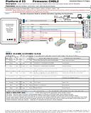
In the thumbnail below. I want to confirm that the areas circled in red are as simple as finding a resistor (or a combination of resistors) that matches the resistance circled and solder them inline between the connections. Yes or no?
to diy or not to diy alarm - Page 2 - Last Post -- posted image.
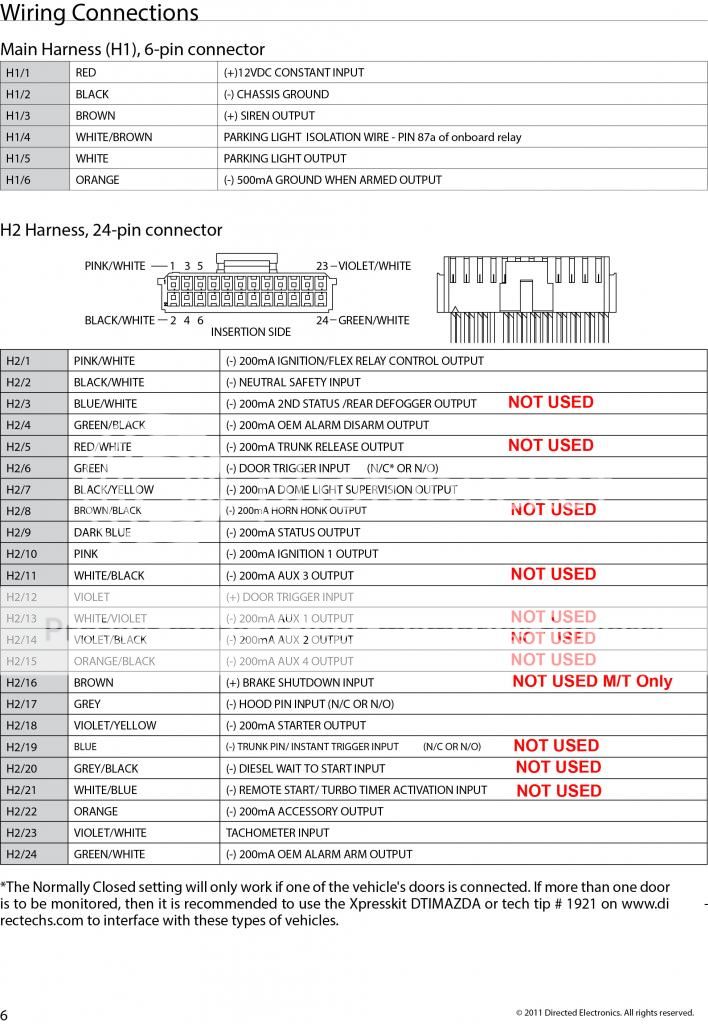
In this thumbnail below, notice the circles areas again. This is from the manual of the Viper 5704. What are they suggesting in the circled areas? For example (-)200ma?;
to diy or not to diy alarm - Page 2 - Last Post -- posted image.
Finally, talking about the bypass modules. I understand that these are needed to bypass the factory security systems. But it also 'appears' to me that this simplifies the installation regarding the door unlock/lock functions. I am not biased towards this module, but in the thumbnail below for example it doesn't show more than a dozen connections to be made.
to diy or not to diy alarm - Page 2 - Last Post -- posted image.
In closing, if I am confident in my ability to make the connections suggested in the tech sheet from Direct Wire working in correlation with the factory Dodge Manual and I wanted to pursue this install myself in the future. In addition to the answering of the questions above, what other technical advice can you give TOWARDS the installation? For example; bad choice of module, bad choice of alarm, you will also need a flux capacitor etc. etc.
Again... thanks for all the help so far and sorry for the long post.
KPierson 
Platinum - Posts: 3,527
Platinum spaceThis member consistently provides reliable informationspace
Joined: April 14, 2005
Location: Ohio, United States
Posted: January 05, 2014 at 9:59 AM / IP Logged  
For the first attachment yes you will need the specified resistor soldered inline with a (-) output from the brain. Whenever I use resistors I make sure I add some support to the leads of the resistors as they are generally somewhat fragile. What I generally do is solder the resistor inline and then before I tape over it I lay a piece of wire next to it. The wire offers support to the resistor legs.
For the second attachment the manual is telling you what type of output / input each wire is. The (-) 200mA listing for outputs basically is telling you that it is a low current output and for any significant power a relay must be used. The (+) door trigger is intended for vehicles with door pins that switch to 12vdc instead of ground (somewhat rare but they do exist). Most installations use either the (-) or the (+) but very rarely use both (sometimes the other one is used as an AUX trigger for the alarm).
If you are going to use a data module make sure it is programmed for your vehicle. If you are buying online double check that they are willing to program it for your vehicle. If the module shows up without the correct firmware on it you'll be dead in the water.
Kevin Pierson
steenm 
Member - Posts: 19
Member spacespace
Joined: December 22, 2013
Location: Florida, United States
Posted: January 05, 2014 at 8:54 PM / IP Logged  
KPierson wrote:
For the first attachment yes you will need the specified resistor soldered inline with a (-) output from the brain. Whenever I use resistors I make sure I add some support to the leads of the resistors as they are generally somewhat fragile. What I generally do is solder the resistor inline and then before I tape over it I lay a piece of wire next to it. The wire offers support to the resistor legs.
For the second attachment the manual is telling you what type of output / input each wire is. The (-) 200mA listing for outputs basically is telling you that it is a low current output and for any significant power a relay must be used. The (+) door trigger is intended for vehicles with door pins that switch to 12vdc instead of ground (somewhat rare but they do exist). Most installations use either the (-) or the (+) but very rarely use both (sometimes the other one is used as an AUX trigger for the alarm).
If you are going to use a data module make sure it is programmed for your vehicle. If you are buying online double check that they are willing to program it for your vehicle. If the module shows up without the correct firmware on it you'll be dead in the water.
Thank you sir for all the info. I do appreciate it. Could you elaborate a little more on this:
"The (-) 200mA listing for outputs basically is telling you that it is a low current output and for any significant power a relay must be used."
For instance, let's use this for example out of the installation manual:
'(-) 200mA HORN HONK OUTPUT'
Essentially, what would you end up doing with this BROWN / Black wire?
Thanks again...
KPierson 
Platinum - Posts: 3,527
Platinum spaceThis member consistently provides reliable informationspace
Joined: April 14, 2005
Location: Ohio, United States
Posted: January 05, 2014 at 11:42 PM / IP Logged  
You could hook that up to the horn honk wire in the vehicle. Generally, though, a siren is used. If the data sheet for your vehicle shows that the horn wire is a (-) trigger then most likely you can hook the horn output directly to the wire (I would verify with a current meter first). If the horn wire is shown as being positive you would need a relay.
Kevin Pierson
steenm 
Member - Posts: 19
Member spacespace
Joined: December 22, 2013
Location: Florida, United States
Posted: January 06, 2014 at 6:08 AM / IP Logged  
KPierson wrote:
You could hook that up to the horn honk wire in the vehicle. Generally, though, a siren is used. If the data sheet for your vehicle shows that the horn wire is a (-) trigger then most likely you can hook the horn output directly to the wire (I would verify with a current meter first). If the horn wire is shown as being positive you would need a relay.
Gotchya, makes perfect sense. So being that the horn signal shows a (-) polarity on the tech sheet from DirectWire, and no resistance value it can hook up directly to the Viper wire but most will not use that connection and use the siren correct?
Looking at the Viper 5704, and looking to install this into a 2008 Dodge Ram 1500 Automatic Transmission. What are thoughts about the instructions below? I have posted the NOT USED notes where I believe I would not need any connections. Do you agree?
to diy or not to diy alarm - Page 2 - Last Post -- posted image.
Page of 2

Sorry, you can NOT post a reply.
This topic is closed.

  Printable version Printable version Post ReplyPost New Topic
You cannot post new topics in this forum
You cannot reply to topics in this forum
You cannot delete your posts in this forum
You cannot edit your posts in this forum
You cannot create polls in this forum
You cannot vote in polls in this forum

  •  
Search the12volt.com
Follow the12volt.com Follow the12volt.com on Facebook
Sunday, June 16, 2024 • Copyright © 1999-2024 the12volt.com, All Rights Reserved Privacy Policy & Use of Cookies
Disclaimer: *All information on this site ( the12volt.com ) is provided "as is" without any warranty of any kind, either expressed or implied, including but not limited to fitness for a particular use. Any user assumes the entire risk as to the accuracy and use of this information. Please verify all wire colors and diagrams before applying any information.

Secured by Sectigo
the12volt.com spacer
Support the12volt.com
Top
the12volt.com spacer