the12volt.com spacer
icon

alarm expert please help me


Post ReplyPost New Topic
< Prev Topic Next Topic >
Skyvan 
Member - Posts: 8
Member spacespace
Joined: December 16, 2004
Location: United States
Posted: December 16, 2004 at 7:15 PM / IP Logged  

Hello

I try to install the alarm myself this is the first time i do this. I have a alarm with remote starter everything are finish but i'am stuck at this option please look at the picture . i'am too poor to have  scaner so i draw it as much as i can please help me i do not know which wire go with which.. i know GRAY connect to YELLOW but other than that i'am stuck pleaseee help me

thanks you

alarm expert please help me - Last Post -- posted image.

auex 
Platinum - Posts: 5,041
Platinum spaceThis member has made a donation to the12volt.com. Click here for more info.spacespace
Joined: December 23, 2002
Location: Arizona, United States
Posted: December 16, 2004 at 7:25 PM / IP Logged  
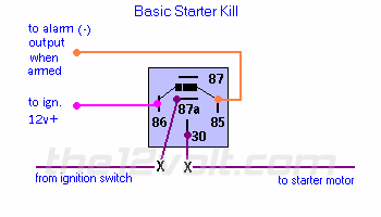
Wow, your paint skills suck. The gray will go to the ground when armed wire from the alarm, the black will go to a source of true ignition, and the greens go to one end of the cut starter wire. At any rate here is a diagram you need to follow.
alarm expert please help me - Last Post -- posted image.
Certified Security Specialist
Always check info with a digital multimeter.
I promise to be good.
Tell Darwin I sent you.
I've been sick lately, sorry I won't be on much.
Skyvan 
Member - Posts: 8
Member spacespace
Joined: December 16, 2004
Location: United States
Posted: December 16, 2004 at 7:32 PM / IP Logged  
Thanks please let me confirm one thing. Yellow go with Gray, Black, White go with bottom GREEN. then Bottom Green go to Ignition.  Then the top Green go to the other end of the cut out ignition is this correct ?
auex 
Platinum - Posts: 5,041
Platinum spaceThis member has made a donation to the12volt.com. Click here for more info.spacespace
Joined: December 23, 2002
Location: Arizona, United States
Posted: December 16, 2004 at 10:31 PM / IP Logged  
Your diagram is wrong. One of the green wires goes to one end of the cut starter wire, not ignition, the other green goes to the other end of the cut starter wire. Hook the grey wire up to the starter kill negative 500ma wire (what ever color that wire is of the alarm). The black wire (according to your diagram) in the relay diagram would go to ign, a wire that has power in run and start only or the white "key on" signal +12V.
Certified Security Specialist
Always check info with a digital multimeter.
I promise to be good.
Tell Darwin I sent you.
I've been sick lately, sorry I won't be on much.

Sorry, you can NOT post a reply.
This topic is closed.

  Printable version Printable version Post ReplyPost New Topic
You cannot post new topics in this forum
You cannot reply to topics in this forum
You cannot delete your posts in this forum
You cannot edit your posts in this forum
You cannot create polls in this forum
You cannot vote in polls in this forum

  •  
Search the12volt.com
Follow the12volt.com Follow the12volt.com on Facebook
Sunday, June 9, 2024 • Copyright © 1999-2024 the12volt.com, All Rights Reserved Privacy Policy & Use of Cookies
Disclaimer: *All information on this site ( the12volt.com ) is provided "as is" without any warranty of any kind, either expressed or implied, including but not limited to fitness for a particular use. Any user assumes the entire risk as to the accuracy and use of this information. Please verify all wire colors and diagrams before applying any information.

Secured by Sectigo
the12volt.com spacer
Support the12volt.com
Top
the12volt.com spacer