the12volt.com spacer
icon

power locks civic dx 96


Post ReplyPost New Topic
< Prev Topic Next Topic >
rpmbxdj 
Member - Posts: 13
Member spacespace
Joined: January 09, 2008
Location: New York, United States
Posted: January 09, 2008 at 11:02 PM / IP Logged  
Hey guys. I recently purchased a 96 civic dx( which has no power anything!), the previous owner had put 2000 civic ex doors on, but the p.windows and locks were never connected! I managed to make the power windows work using my own custon wiring and fuses. Now my question is this: Is the power lock install easier if i just forget about trying to use oem honda parts and use an aftermarket power lock system with its own actuators? Secondly, I have a autopage rs-900 alarm installed also, will i have to use a relay to get the doors to unlock/lock with an aftermarket powerlock system? Anyone's input will be GREATLY APPRECIATED!
Honda 4 Life!
DJ 4 Life!!
swerve 
Copper - Posts: 149
Copper spacespace
Joined: January 10, 2007
Location: Oregon, United States
Posted: January 22, 2008 at 12:10 AM / IP Logged  

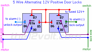
if the locks are already installed then all you have to do is get the wires that go to them and wire them up with relays, then take the lock and unlock wires from the autopage and hook it up to the relays. its going to be a five-wire relay setup

. power locks civic dx 96 -- posted image.

don't go aftermarket, the honda ones are going to be easier and more reliable.

there should only be two wires coming from the locks all you gotta do is give one side 12+ and the other side ground and see which way it moves. then hook it up accordingly. also you will only need two relays for both sides cuz the door locks don't need that much amperage. i might have forgotten something but thats pretty much it. if you can figure out the pw  you can handle the door locks.

git yer swerve on!
secureauto 
Copper - Posts: 196
Copper spacespace
Joined: January 02, 2003
Location: California, United States
Posted: January 22, 2008 at 2:17 AM / IP Logged  
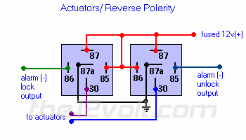
Since the car had no doorlocks previously you're going to have to wire up the doorlocks as if they were aftermarket. (WHITE/ red and blue/red from driver door will go to both 30's on relay diagram) and (WHITE/ red and yellow/red for passenger door).
power locks civic dx 96 -- posted image.
If you want to use the doorlock switches in the door, you have to wire up the GREEN / WHITE(-) and GREEN/ orange(-) wires to the relays. (86 and 85 on diagram). You also have to make sure you ground the third wire at the switches.
ASE Certified
rpmbxdj 
Member - Posts: 13
Member spacespace
Joined: January 09, 2008
Location: New York, United States
Posted: January 24, 2008 at 12:19 AM / IP Logged  
Thank you very much for your help. I will be trying it once it gets a lil warm out here in NYC..lol
Honda 4 Life!
DJ 4 Life!!
rpmbxdj 
Member - Posts: 13
Member spacespace
Joined: January 09, 2008
Location: New York, United States
Posted: February 05, 2008 at 11:56 PM / IP Logged  
Hey Guys, Once again I wanted to Thank You for your inputs on my powerlock dilemna. However there is one thing that I noticed while looking at my civic's wiring diagram. Do I have to use aftermarket relays as u guys prescribed above,if the drivers side door has a door lock control (OEM)module already in it? From looking at the diagram, it looks like u just have to provide a always hot power to the door lock module and make sure that all the wiring is matched correctly and make sure that the GREEN / WHITE wire from module would go to lock output of autopage and the GREEN/ orange wire would go to the unlock output of the alarm. You guys seem like u have some experience in this and ur input would be greatly appreciated.. Thanks RR[
Honda 4 Life!
DJ 4 Life!!
flobee4 
Silver - Posts: 585
Silver spacespace
Joined: January 02, 2004
Location: United States
Posted: February 06, 2008 at 12:45 AM / IP Logged  

on the OEM module it looks like:

WHITE/ green - Constant 12v fused 20amp - Pin 12

Black - Ground - Pin 4

GREEN/ Orange - (-)Unlock from switch - Pin 8

GREEN / WHITE - (-)Lock from switch - Pin 1

WHITE/ Red - Drivers door lock motor as well as passengers door motor - pin 5

blue/red - Drivers door lock motor only - pin 3

yellow/red - Passenger doorlock motor - pin 2

blue/white - comes from the drivers door lock actuator,  this wire provides a (-) lock signal when you lock the doors from outside the car using the key. The (-) signal locks all doors. - Pin 7

Black at the drivers doorlock switch -pin 2 at switch

Black - need to be grounded as well as at the door lock actuator - pin 3 at actuator

I have the whole diagram for the 2000 civic if needed just PM me your email and I'll send it to you.

rpmbxdj 
Member - Posts: 13
Member spacespace
Joined: January 09, 2008
Location: New York, United States
Posted: February 06, 2008 at 9:53 AM / IP Logged  
Thanks Flobee for the post. I already have the haynes manual which has the electrical diagram for the civic so I dont think that I will be needing that right now. Do I have to splice into the pin8 wire(unlock) and hook it up to the autopage and hook up the pin1(lock) to the alarm as well for the alarm to unlock/lock doors during arm/disarm? Also you didnt say if I had to wire up aftermarket relays for this procedure as the other 2 guys stated on the initial postings. Also are the actuators and switches already grounded at the doors or do I have to ground them myself as I did when I hooked up the power windows to this 96 civic DX with 00' Civic EX doors? Sorry for all the questions buddy, but I wana cover all my bases..
Thanx RR
Honda 4 Life!
DJ 4 Life!!
flobee4 
Silver - Posts: 585
Silver spacespace
Joined: January 02, 2004
Location: United States
Posted: February 06, 2008 at 11:13 AM / IP Logged  

Yes the autopage's Lock/unlock wires will just tap into Pin 8 and Pin 1 respectively. No relays needed as they are built into the OEM Power door lock module.  You will have to ground the Black wire at the switch on the drivers door(Pin 2 at the switch).  The actuators will get there ground from the 2 wires going to them, so don't ground the actuators. 

On  the drivers door, there will be a 3rd and 4th wire coming off the actuator.  They are basically for a built in switch that locks all doors when you lock the drivers door.  Lets say you and a passenger get out of the car. Both doors are unlocked because you just got out. You both close the doors. You put your key in the drivers door to lock the drivers door.  If you hook up these switch wires, when you lock the drivers door the passengers door will lock also. This is a factory feature, Since you are hooking up the autopage, and thats really what you will be using to lock the doors, these 2 extra wires are not needed. But if you want its just 2 more connections. 

At the actuator on the drivers door only you will have 4 pins, Pin 1 & 2 control the power to the door lock motor.  Pin 3 & 4 are for the switch on the extra feature I described above. Pin 3 get grounded and Pin 4 of the actuator goes to pin 7 of the OEM control module. Pin 1 = WHITE/ red, pin 2=Blue/red, pin 3=black, pin 4=blue/white

rpmbxdj 
Member - Posts: 13
Member spacespace
Joined: January 09, 2008
Location: New York, United States
Posted: February 06, 2008 at 5:39 PM / IP Logged  
Thanks Flobee for all that great info. I will keep u posted on my progress on my powerlock project.
RR
Honda 4 Life!
DJ 4 Life!!
jaybizz 
Member - Posts: 30
Member spacespace
Joined: February 02, 2008
Location: New York, United States
Posted: February 07, 2008 at 12:57 AM / IP Logged  

hey whatz up, what part of the city u from?

alarm king
Page of 2

  Printable version Printable version Post ReplyPost New Topic
You cannot post new topics in this forum
You cannot reply to topics in this forum
You cannot delete your posts in this forum
You cannot edit your posts in this forum
You cannot create polls in this forum
You cannot vote in polls in this forum

  •  
Search the12volt.com
Follow the12volt.com Follow the12volt.com on Facebook
Friday, April 19, 2024 • Copyright © 1999-2024 the12volt.com, All Rights Reserved Privacy Policy & Use of Cookies
Disclaimer: *All information on this site ( the12volt.com ) is provided "as is" without any warranty of any kind, either expressed or implied, including but not limited to fitness for a particular use. Any user assumes the entire risk as to the accuracy and use of this information. Please verify all wire colors and diagrams before applying any information.

Secured by Sectigo
the12volt.com spacer
Support the12volt.com
Top
the12volt.com spacer