the12volt.com spacer
icon

push button switch to lock / unlock doors


Post ReplyPost New Topic
< Prev Topic Next Topic >
sygad 
Member - Posts: 7
Member spacespace
Joined: March 06, 2003
Location: United Kingdom
Posted: March 06, 2003 at 7:57 AM / IP Logged  

I currently use 2 switches, each with a feed from the negative on the battery to control the lock and unlocking of my doors,  I asked the alarm guy to show which wires to connect to, but he couldn't tell me how to do it with only 1 switch

Is there a way of using 1 push to make non latching switch that when pressed once will lock the doors and when pressed again will inlock the doors, this doesn't need any connection to the alarm as i just want a button on the dashboard that locks and unlocks the doors

Cheers for any help received, schematics and real simple explanations would be greatly appreciated

Daz (UK)

p.s. I have  a '95 peugeot 306

cpgoose 
Gold - Posts: 1,098
Gold spacespace
Joined: July 08, 2002
Location: United States
Posted: March 07, 2003 at 7:45 AM / IP Logged  
hmmm, not sure if this is what you're looking for, but I did the same thing using a "non-locking rocker switch". It's a switch, not a pushbutton, that you can switch up (I used that for unlock) or down (lock), and it always falls back to the middle. I'll see if I can find the diagram I used for hooking it up to the relays and the alarm.
sygad 
Member - Posts: 7
Member spacespace
Joined: March 06, 2003
Location: United Kingdom
Posted: March 07, 2003 at 8:14 AM / IP Logged  

thanx for the reply but not really m8,

i already had the idea of the rocker, but it is fundamentally the same as i already have,  2 switches just combined into 1 housing

The single switch idea I saw it  in my mates car (citroen c3) and its well smart and would really like the same function in mine, just 1 switch, push to make which handles the locking and unlocking alternately.

was reading another thread which mentioned a set / reset logic circuit, not sure if this is what i need, also checked out relay apps and that nearly looked promising but required 2 wires (lock, unlock) from the unspecified switch, which i presumed must have been a rocker switch.

this circuit doesn't have to be connected in any way to the alarm just a simple swtich closing the door type circuit

cheers but the search continues

daz

the12volt 
Administrator - Posts: 3,955
Administrator spaceThis member has made a donation to the12volt.com. Click here for more info.spaceThis member has been recognized as an authority in Electrical Theory. Click here for more info.spaceThis member has been recognized as an authority in Mobile Audio and Video. Click here for more info.spaceThis member has been recognized as an authority in Mobile Security and Convenience. Click here for more info.spacespace
Joined: March 07, 2002
Location: Louisiana, United States
Posted: March 07, 2003 at 8:50 AM / IP Logged  

You'll need to add a latching relay  http://www.hosfelt.com/en-us/dept_111.html  (near bottom of page)  to work with the type of switch you want to use to lock and unlock your doors. Each time you press the switch it will alternately send a ground (or positive pulse, whichever you need) to the existing lock and unlock relay. 

push button switch to lock / unlock doors -- posted image. the12volt • Support the12volt.com
sygad 
Member - Posts: 7
Member spacespace
Joined: March 06, 2003
Location: United Kingdom
Posted: March 07, 2003 at 9:13 AM / IP Logged  

when you say "add" would this be to other relays, or is this the only relay i use?

the switches i use currently feed into the central locking "brain" and that handles the rest of the operation, my circuit, if you could call it that is nothing more comlicated than a piece of wire from the negative terminal on the battery going to 2 swtiches that continue to 2 wires my alarm guy pointed out control the locking and unlocking, located under the carpet by the drivers door, i don't use relays at the moment so was wondering is this the only one i need

with it being a latched relay, when i press the button once will the relay keep it active (for want of more technically accurate word) so the central locking sees it as the button being continuosly pressed

if you have any diagrams that could better explain this i would be extremely grateful

regards

daz

the12volt 
Administrator - Posts: 3,955
Administrator spaceThis member has made a donation to the12volt.com. Click here for more info.spaceThis member has been recognized as an authority in Electrical Theory. Click here for more info.spaceThis member has been recognized as an authority in Mobile Audio and Video. Click here for more info.spaceThis member has been recognized as an authority in Mobile Security and Convenience. Click here for more info.spacespace
Joined: March 07, 2002
Location: Louisiana, United States
Posted: March 07, 2003 at 9:36 AM / IP Logged  

Yes, you will have to add this to alternately send a pulse to the lock and unlock relays. The "locking brain" contains these relays. The two wires your alarm guy pointed out to you are the leads going to the coils of the lock and unlock relays. The output of the switch through the latching relay will supply a pulse for each alternately with each press of the switch.

When the coil of the latching relay is energized and released, two contacts have continuity ( the common and one other terminal, call it "A"), when the coil is energized and released again two contacts will have continuity ( the common and a different terminal, call it "B" ) . If you use the output of the switch to energize the coil of the latching relay and also connect it to the common terminal of the latching relay, either output (A or B) from the latching relay will only show the same output as the switch for as long as the switch is pressed.  "A" would connect to the lock lead pointed out to you. "B" would connect to the unlock lead pointed out to you. If I have time this evening or this weekend, I'll draw a diagram for you if someone doesn't post one first ;). 

push button switch to lock / unlock doors -- posted image. the12volt • Support the12volt.com
sygad 
Member - Posts: 7
Member spacespace
Joined: March 06, 2003
Location: United Kingdom
Posted: March 07, 2003 at 9:40 AM / IP Logged  

cheers for taking the time to answer, i will have a another look at relay apps to try and get my head round the workings of the latching relay, if you could spare the time to knock up a quick diagram that would be very much appreciated, as you can probably gather electronics is not my strong point and i don't want to blow anything up

cheers and thanks once again

daz

MCubed45 
Copper - Posts: 65
Copper spacespace
Joined: February 27, 2003
Location: United States
Posted: March 07, 2003 at 5:29 PM / IP Logged  
hey 12volt, a little off topic but you know w/ latching relays, does the same pin numbering convention apply?  or is it diff. b/c technically everytime you energize the coil your NO and NC contacts switch...  like 87a is usually your NC contact on a regular relay but after you energize the coil once the other terminal is NC and the one that was your '87a' is now NO.  haha that makes it confusing.  anyways just wondering if you know how they number the pins on latching relay.
the12volt 
Administrator - Posts: 3,955
Administrator spaceThis member has made a donation to the12volt.com. Click here for more info.spaceThis member has been recognized as an authority in Electrical Theory. Click here for more info.spaceThis member has been recognized as an authority in Mobile Audio and Video. Click here for more info.spaceThis member has been recognized as an authority in Mobile Security and Convenience. Click here for more info.spacespace
Joined: March 07, 2002
Location: Louisiana, United States
Posted: March 08, 2003 at 5:02 PM / IP Logged  
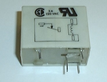
Hi MCubed45, no, they do not have the same numbering system. These are PCB (Printed Circuit Board) type relays and will differ based on manufacturer and specific type if numbered or labeled at all. Most will include a diagram on one side of the relay showing the pin layout for the coil(s) and contacts. When you purchase a latching relay, make sure that it is a mechanical latching relay and does not require a reversal of polarity for set and reset positions. Unlike the automotive relays you are familiar with, these kinda work like a ball point pen. When you energize the coil of the relay momentarily it will either close or open the contacts and remain that way without voltage across the coil just like when you push the button on the top of the pen and let go, the writing part will either come out and stay out or go in and stay in. When I go into to work Monday morning, I'll take a picture of one and post it here.
push button switch to lock / unlock doors -- posted image. the12volt • Support the12volt.com
the12volt 
Administrator - Posts: 3,955
Administrator spaceThis member has made a donation to the12volt.com. Click here for more info.spaceThis member has been recognized as an authority in Electrical Theory. Click here for more info.spaceThis member has been recognized as an authority in Mobile Audio and Video. Click here for more info.spaceThis member has been recognized as an authority in Mobile Security and Convenience. Click here for more info.spacespace
Joined: March 07, 2002
Location: Louisiana, United States
Posted: March 10, 2003 at 2:04 PM / IP Logged  

Here's a picture of a latching relay. This one only has one set of terminals that are either closed or opened. The coil only needs to be energized momentarily and released to change the continuity of the two terminals. So when you energize the coil the first time and release it, the two terminals remain closed. When you energize the coil a second time and release it, the two terminals remain open.

push button switch to lock / unlock doors -- posted image.

push button switch to lock / unlock doors -- posted image. the12volt • Support the12volt.com
Page of 2

  Printable version Printable version Post ReplyPost New Topic
You cannot post new topics in this forum
You cannot reply to topics in this forum
You cannot delete your posts in this forum
You cannot edit your posts in this forum
You cannot create polls in this forum
You cannot vote in polls in this forum

  •  
Search the12volt.com
Follow the12volt.com Follow the12volt.com on Facebook
Thursday, May 2, 2024 • Copyright © 1999-2024 the12volt.com, All Rights Reserved Privacy Policy & Use of Cookies
Disclaimer: *All information on this site ( the12volt.com ) is provided "as is" without any warranty of any kind, either expressed or implied, including but not limited to fitness for a particular use. Any user assumes the entire risk as to the accuracy and use of this information. Please verify all wire colors and diagrams before applying any information.

Secured by Sectigo
the12volt.com spacer
Support the12volt.com
Top
the12volt.com spacer