the12volt.com spacer
icon

omega ultimate edp wiring diagram


Post ReplyPost New Topic
< Prev Topic Next Topic >
seve9ineimpala 
Member - Posts: 5
Member spacespace
Joined: November 14, 2005
Location: Canada
Posted: August 06, 2008 at 4:03 PM / IP Logged  

hey guys, i just recently purchased a 2006 gmc canyon. It did not have power locks from the factory so i decided to wire in some accuators. Anyways i got everything done and than i pulled down the alarm to finish up the wiring. The alarm is an omega ultimate-edp (which was installed before i bought the truck), but does not have any labeling on it to where i would tap in for the door locks. i have searched the net and i can't seem to find a wiring diagram for it anywhere. If anyone can hook me up with a diagram or some insight it would be greatly appreciated.

thanks G,

chillin420 
Copper - Posts: 236
Copper spacespace
Joined: March 27, 2008
Location: California, United States
Posted: August 06, 2008 at 5:11 PM / IP Logged  
it is probably going to be in a 3 pin molex connector.  going to be blue and green wires most likely
you can do it....
advanced MECP, lol does it really matter....
patience is a virtue
twistedp 
Member - Posts: 38
Member spacespace
Joined: July 10, 2008
Location: Texas, United States
Posted: August 06, 2008 at 6:05 PM / IP Logged  

omega ultimate edp wiring diagram -- posted image.
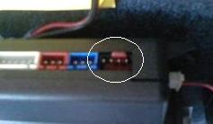
this pic is from a al-2000-edp but yours should look very similar if not the same.

The locks connection should have a 4 pin connector as above.

omega ultimate edp wiring diagram -- posted image.
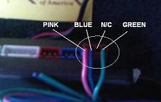
The pins should be connected as shown. (N/C means no connection.)

pink = (-) 1st door unlock (for 2 stage unlock), blue = (-) unlock or (+) lock, green = (-)lock or (+)unlock.

Twisted Performance
seve9ineimpala 
Member - Posts: 5
Member spacespace
Joined: November 14, 2005
Location: Canada
Posted: August 06, 2008 at 10:02 PM / IP Logged  
thanks alot guys this is just what i was looking for
seve9ineimpala 
Member - Posts: 5
Member spacespace
Joined: November 14, 2005
Location: Canada
Posted: October 18, 2008 at 9:04 PM / IP Logged  

ok guys so i finally got a chance to take some picture, i went and tried to wire up driver side accuator with a pair of relays using the diagrams i found on the site, but i can not get them to work. If any one can shed some light on which inputs in the picture i uploaded are the right ones for wiring the accuators, it would be greatly appreciated.

omega ultimate edp wiring diagram -- posted image.

twistedp 
Member - Posts: 38
Member spacespace
Joined: July 10, 2008
Location: Texas, United States
Posted: October 20, 2008 at 12:01 PM / IP Logged  
the wires pictured are not for the door locks. the door lock wires are a thinner gauge. the previous installer probably did not connect the plug containing the wires for the door locks. it should be one of the empty plugs on the side of the unit. looking at the picture, on the left side where there is a small four wire plug for the shock sensor. to make a long story short, you will first need the plug for the door locks. once you get one, you will be able to wire the relays according to the actuator diagram on this site.
Twisted Performance
seve9ineimpala 
Member - Posts: 5
Member spacespace
Joined: November 14, 2005
Location: Canada
Posted: October 21, 2008 at 2:20 PM / IP Logged  
thanks man, i was just thrown off because that wide connector says doors on it with the negative and positive trigger markings on it. im gonna assume that its meant for vehicles with factory keyless entry. anyways thanks for the help man i appreciate it.

Sorry, you can NOT post a reply.
This topic is closed.

  Printable version Printable version Post ReplyPost New Topic
You cannot post new topics in this forum
You cannot reply to topics in this forum
You cannot delete your posts in this forum
You cannot edit your posts in this forum
You cannot create polls in this forum
You cannot vote in polls in this forum

  •  
Search the12volt.com
Follow the12volt.com Follow the12volt.com on Facebook
Thursday, April 25, 2024 • Copyright © 1999-2024 the12volt.com, All Rights Reserved Privacy Policy & Use of Cookies
Disclaimer: *All information on this site ( the12volt.com ) is provided "as is" without any warranty of any kind, either expressed or implied, including but not limited to fitness for a particular use. Any user assumes the entire risk as to the accuracy and use of this information. Please verify all wire colors and diagrams before applying any information.

Secured by Sectigo
the12volt.com spacer
Support the12volt.com
Top
the12volt.com spacer