the12volt.com spacer
icon

08 ford superduty aux jack input pinout


Post ReplyPost New Topic
< Prev Topic Next Topic >
davidachew 
Member - Posts: 31
Member spacespace
Joined: January 14, 2005
Location: United States
Posted: August 25, 2008 at 4:47 PM / IP Logged  

Does anyone know the pinout for the 4 wire aux port on a 2008 ford superduty? No one seems to make any type of inline harnes and I want the install of a external xm sat reciever look clean. (no wires pluged into the external aux jack)

Thanks

i am an idiot 
Platinum - Posts: 13,670
Platinum spaceThis member consistently provides reliable informationspace
Joined: September 21, 2006
Location: Louisiana, United States
Posted: August 25, 2008 at 5:06 PM / IP Logged  
Does the aux input jack plug into this 4 pin harness?    Do you have a Meter?
davidachew 
Member - Posts: 31
Member spacespace
Joined: January 14, 2005
Location: United States
Posted: August 26, 2008 at 8:47 AM / IP Logged  

Yes and Yes, but its an input... im assuming the 4 wires are as follows left +, - and right +,-

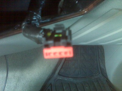
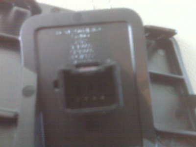
Here are some pics

08 ford superduty aux jack input pinout -- posted image.

08 ford superduty aux jack input pinout -- posted image.

i am an idiot 
Platinum - Posts: 13,670
Platinum spaceThis member consistently provides reliable informationspace
Joined: September 21, 2006
Location: Louisiana, United States
Posted: August 26, 2008 at 1:49 PM / IP Logged  

I should have been a little more clear.  Is there an 1/8 inch input jack that the harness plugs into?

If it does, go to Radio Shack and purchase an 1/8 inch stereo male to 1/8 inch stereo male adapter.  They are a common item for the rocket scientists at any of their locations.  Plug one end into the jack of the vehicle.   now using your ohm meter touch and hold one lead to the tip of the other end of the cable.  Now touch the other meter lead to the 4 wires on the back of the plug. (one wire at a time of course)  When you find the wire that is connected to that.  That would be the right signal positive wire.  now move the lead to the piece of metal between the 2 black rings of the plug.  Now meter the remaining 3 wires.  The one that is common with this terminal is going to be your left positive signal wire.  The ground connection of the plug is the metal piece between the base of the connector and the first black ring.  Hold meter lead to this and test the 2 remaining wires.  This is the ground or shield connection.


Sorry, you can NOT post a reply.
This topic is closed.

  Printable version Printable version Post ReplyPost New Topic
You cannot post new topics in this forum
You cannot reply to topics in this forum
You cannot delete your posts in this forum
You cannot edit your posts in this forum
You cannot create polls in this forum
You cannot vote in polls in this forum

  •  
Search the12volt.com
Follow the12volt.com Follow the12volt.com on Facebook
Saturday, May 4, 2024 • Copyright © 1999-2024 the12volt.com, All Rights Reserved Privacy Policy & Use of Cookies
Disclaimer: *All information on this site ( the12volt.com ) is provided "as is" without any warranty of any kind, either expressed or implied, including but not limited to fitness for a particular use. Any user assumes the entire risk as to the accuracy and use of this information. Please verify all wire colors and diagrams before applying any information.

Secured by Sectigo
the12volt.com spacer
Support the12volt.com
Top
the12volt.com spacer