


xk01 disarm with lock cylinder turn gm
Home /
the12volt's Install Bay /
Car Security and Convenience / xk01 disarm with lock cylinder turn gm ( Topic Closed)


Posted: February 05, 2009 at 8:50 AM / IP Logged


Posted: February 05, 2009 at 9:13 PM / IP Logged
Posted: February 06, 2009 at 7:32 AM / IP Logged
Posted: February 06, 2009 at 11:06 PM / IP Logged
Posted: February 06, 2009 at 11:20 PM / IP Logged
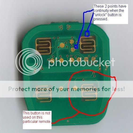 Note the labeled jumper points. Since this particular PC board has 2 layers, the jumpers go between the front and back layer.
Below is my remote viewed externally:
Note the labeled jumper points. Since this particular PC board has 2 layers, the jumpers go between the front and back layer.
Below is my remote viewed externally:
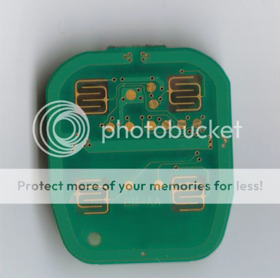
 Here's the first image without the text so you can see the traces a bit better:
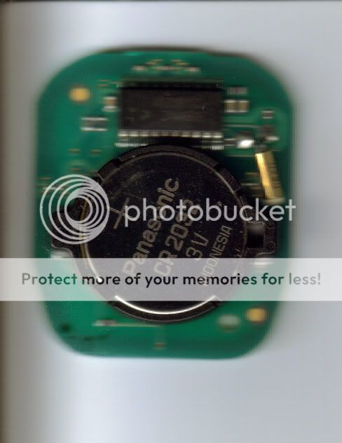
 The back side of the remote:
Posted: February 07, 2009 at 12:27 AM / IP Logged
Posted: February 09, 2009 at 7:10 AM / IP Logged

Posted: February 09, 2009 at 7:30 AM / IP Logged
Sorry, you can NOT post a reply.
This topic is closed.
 Printable version
| You cannot post new topics in this forum You cannot reply to topics in this forum You cannot delete your posts in this forum You cannot edit your posts in this forum You cannot create polls in this forum You cannot vote in polls in this forum |

| Search the12volt.com |
Follow the12volt.com 
Saturday, March 28, 2026 • Copyright © 1999-2026 the12volt.com, All Rights Reserved • Privacy Policy & Use of Cookies

Saturday, March 28, 2026 • Copyright © 1999-2026 the12volt.com, All Rights Reserved • Privacy Policy & Use of Cookies
Disclaimer:
*All information on this site ( the12volt.com ) is provided "as is" without any warranty of any kind, either expressed or implied, including but not limited to fitness for a particular use. Any user assumes the entire risk as to the accuracy and use of this information. Please
verify all wire colors and diagrams before applying any information.
