


2001 audi a8 bose symphony radio
Home /
the12volt's Install Bay /
Vehicle Wiring Information & File Requests / 2001 audi a8 bose symphony radio ( Topic Closed)


Posted: March 31, 2009 at 12:15 PM / IP Logged


Posted: March 31, 2009 at 12:33 PM / IP Logged
Posted: March 31, 2009 at 1:11 PM / IP Logged
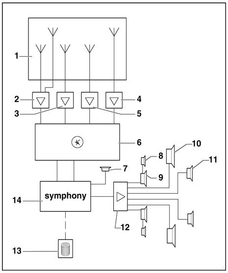 1 - Rear window antennas
2 - Antenna amplifier behind left D-pillar trim (top)
3 - Antenna amplifier below rear parcel shelf on luggage compartment bulkhead (left)
4 - Antenna amplifier behind right D-pillar trim (top)
5 - Antenna amplifier below rear parcel shelf on luggage compartment bulkhead (right)
6 - Control module for antenna selection behind left C-pillar trim (bottom)
7 - Hands-free speaker installed in left B-pillar trim (telephone only through m.y. 2001 and telephone/telematics from m.y. 2002)
8 - Tweeter installed in front door trim (top)
9 - Bass speaker installed in front door trim (bottom)
10 - Bass speaker installed in rear parcel shelf
11 - Mid-range/tweeter installed in rear door trim (bottom)
12 - BOSE-end amplifier installed in luggage compartment (left rear)
13 - CD changer (optional) installed in luggage compartment (left rear)
14 - Symphony radio
Terminal assignment of multi-pin connectors I, II, III, IV at rear of radio
Note: Terminals which are not listed are vacant/unassigned.
1 - Rear window antennas
2 - Antenna amplifier behind left D-pillar trim (top)
3 - Antenna amplifier below rear parcel shelf on luggage compartment bulkhead (left)
4 - Antenna amplifier behind right D-pillar trim (top)
5 - Antenna amplifier below rear parcel shelf on luggage compartment bulkhead (right)
6 - Control module for antenna selection behind left C-pillar trim (bottom)
7 - Hands-free speaker installed in left B-pillar trim (telephone only through m.y. 2001 and telephone/telematics from m.y. 2002)
8 - Tweeter installed in front door trim (top)
9 - Bass speaker installed in front door trim (bottom)
10 - Bass speaker installed in rear parcel shelf
11 - Mid-range/tweeter installed in rear door trim (bottom)
12 - BOSE-end amplifier installed in luggage compartment (left rear)
13 - CD changer (optional) installed in luggage compartment (left rear)
14 - Symphony radio
Terminal assignment of multi-pin connectors I, II, III, IV at rear of radio
Note: Terminals which are not listed are vacant/unassigned.
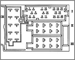 20-pin multi-pin connector I
1 - Line out - left rear (BOSE amplifier)
2 - Line out - right rear (BOSE amplifier)
3 - NF-Ground (GND) (BOSE amplifier)
4 - Line out - left front (BOSE amplifier)
5 - Line out - right front (BOSE amplifier)
6 - Switched B+ (BOSE amplifier)
7 - CAN-Bus High (display) from m.y. 2002
8 - Clock-signal (through m.y. 2001)
9 - Data-signal (through m.y. 2001)
10 - NOTE: Enable-signal (through m.y. 2001) OR CD Ground (GND) from m.y. 2002
11 - Multi-function steering wheel through m.y. 2001
12 - CAN-Bus Low (display) from m.y. 2002
13 - CD-Bus data in (CD-changer)
14 - CD-Bus Data out (CD-changer)
15 - CD-clock (CD-changer)
16 - Continuous B+ (CD-changer)
17 - CD-switched B+ (CD-changer)
18 - CD-NF Ground (GND) (CD-changer)
19 - Signal wire left channel (CD-NF-L)
20 - Signal wire right channel (CD-NF-R)
8-pin multi-pin connector II, brown
5 - Hands-free speaker (through m.y. 2001)
6 - Hands-free speaker (through m.y. 2001)
8-pin multi-pin connector III, black
1 -
Gala (RPM signal) through m.y. 2001
BOSE coding from m.y. 2002
2 -
NF-Telephone muting
Anti-theft alarm Ground (GND) from m.y. 2002
3 - Diagnostic connection (K-wire)
4 - Terminal 86s - connection for switching on and off via ignition switch (S-contact) through m.y. 2001
6 - Illumination (terminal 58d) through m.y. 2001
7 - Battery + (terminal 30)
8 - Ground (GND) (terminal 31)
10-pin multi-pin connector IV, red
1 - Telephone muting
2 - Terminal 15 through m.y. 2001
3 - Telephone (NF+) (not for navigation equipment)
4 - Telephone (NF-) (not for navigation equipment)
5 - Navigation (NF+)
6 - Navigation (NF-)
7 - Navigation control wire
9 - Illumination display (terminal 58d) through m.y. 2001
Complex, but most of it can be eliminated I'm thinking.
20-pin multi-pin connector I
1 - Line out - left rear (BOSE amplifier)
2 - Line out - right rear (BOSE amplifier)
3 - NF-Ground (GND) (BOSE amplifier)
4 - Line out - left front (BOSE amplifier)
5 - Line out - right front (BOSE amplifier)
6 - Switched B+ (BOSE amplifier)
7 - CAN-Bus High (display) from m.y. 2002
8 - Clock-signal (through m.y. 2001)
9 - Data-signal (through m.y. 2001)
10 - NOTE: Enable-signal (through m.y. 2001) OR CD Ground (GND) from m.y. 2002
11 - Multi-function steering wheel through m.y. 2001
12 - CAN-Bus Low (display) from m.y. 2002
13 - CD-Bus data in (CD-changer)
14 - CD-Bus Data out (CD-changer)
15 - CD-clock (CD-changer)
16 - Continuous B+ (CD-changer)
17 - CD-switched B+ (CD-changer)
18 - CD-NF Ground (GND) (CD-changer)
19 - Signal wire left channel (CD-NF-L)
20 - Signal wire right channel (CD-NF-R)
8-pin multi-pin connector II, brown
5 - Hands-free speaker (through m.y. 2001)
6 - Hands-free speaker (through m.y. 2001)
8-pin multi-pin connector III, black
1 -
Gala (RPM signal) through m.y. 2001
BOSE coding from m.y. 2002
2 -
NF-Telephone muting
Anti-theft alarm Ground (GND) from m.y. 2002
3 - Diagnostic connection (K-wire)
4 - Terminal 86s - connection for switching on and off via ignition switch (S-contact) through m.y. 2001
6 - Illumination (terminal 58d) through m.y. 2001
7 - Battery + (terminal 30)
8 - Ground (GND) (terminal 31)
10-pin multi-pin connector IV, red
1 - Telephone muting
2 - Terminal 15 through m.y. 2001
3 - Telephone (NF+) (not for navigation equipment)
4 - Telephone (NF-) (not for navigation equipment)
5 - Navigation (NF+)
6 - Navigation (NF-)
7 - Navigation control wire
9 - Illumination display (terminal 58d) through m.y. 2001
Complex, but most of it can be eliminated I'm thinking.Posted: March 31, 2009 at 1:21 PM / IP Logged
Posted: March 31, 2009 at 1:46 PM / IP Logged
Posted: March 31, 2009 at 2:07 PM / IP Logged

Posted: March 31, 2009 at 3:32 PM / IP Logged
Posted: March 31, 2009 at 4:06 PM / IP Logged
Posted: April 01, 2009 at 11:47 AM / IP Logged
Posted: April 01, 2009 at 12:33 PM / IP Logged
Sorry, you can NOT post a reply.
This topic is closed.
 Printable version
| You cannot post new topics in this forum You cannot reply to topics in this forum You cannot delete your posts in this forum You cannot edit your posts in this forum You cannot create polls in this forum You cannot vote in polls in this forum |

| Search the12volt.com |
Follow the12volt.com 
Tuesday, April 28, 2026 • Copyright © 1999-2026 the12volt.com, All Rights Reserved • Privacy Policy & Use of Cookies

Tuesday, April 28, 2026 • Copyright © 1999-2026 the12volt.com, All Rights Reserved • Privacy Policy & Use of Cookies
Disclaimer:
*All information on this site ( the12volt.com ) is provided "as is" without any warranty of any kind, either expressed or implied, including but not limited to fitness for a particular use. Any user assumes the entire risk as to the accuracy and use of this information. Please
verify all wire colors and diagrams before applying any information.
